INSTALLING A FLUSH MOUNTING DOOR STATION
1. Mount back box S (Fig.2) at 165 cm from ground level (Fig.1);
2. If more than one ush box is needed, connect them by using the plastic spacers provided A (Fig.2);
3. If necessary nish and clean properly the module support xing holes and all other holes B (Fig. 2);
4. A rainshield D (Fig.3 & 4) can be mounted using the xing screws G (Fig.4) to conceal possible wall nishing defects and pro-
tect against rain;
In order to prevent water ingress we highly recommend using a silicon sealant between the wall and the back box
and between the wall and the rainshield D (Fig.3);
5. Remove the xing screws H (Fig.5) and remove the plastic cover E (Fig. 5) of the module support;
6. Insert the modules F (Fig.6) according the required conguration;
7. Insert the microphone of the door unit amplier into the microphone hole X (Fig.7);
8. Secure the modules by retting the plastic cover E (Fig.8) and using the screws H (Fig.8);
9. Insert the hinge I (Fig.9) and x it with the two screws K (Fig.9) provided;
10. Make all connections following accurately the wiring diagram provided. Check the installation and if necessary adjust speech
levels using volume controls L (Fig.9);
11. Lever the support R (Fig.10) upwards and x it to the back box with the screw M (Fig.11) using an alan key P (Fig.11);
12. Conceal the screw using the plastic cover N (Fig.11) provided.
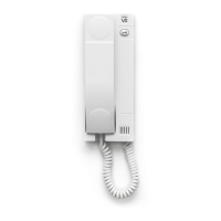
INSTALLING A SURFACE MOUNTING DOOR STATION
Fix the surface box on the wall at a distance of 165 cm between the top of the box and the ground (Fig.1).
In order to prevent water ingress we highly recommend using a silicon sealant between the wall and the back box J
(Fig.12) and around all holes W (Fig.12).
To complete the installation follow the same steps described above for the ush box.
N
ote: if additional holes are made in the box or rainshield, oxidation problems may appear unless the
unprotected metal is coated with a protective paint.
HOW TO REMOVE THE CARD NAME HOLDER
• To avoid damage to the module front plate, tape the side that will be in contact with the screwdriver blade;
• lnsert a at screwdriver into the card-holder hole as shown in Fig. 13;
• Move the screwdriver to the left as shown in Fig. 14 to extract the card name holder;
• Edit the card name then replace it inside the holder and ret: insert the holder inside its housing from the left or right side then
push the other side until it clips into place.
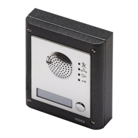
8000 Series Surface and ush mounting door station installation