24
IIMMPPIIAANNTTOO
VVIIDDEEOOCCIITTOOFFOONNIICCOO
nn..........
UUTTEENNTTII
DDeessccrriizziioonnee
Questo impianto permette il collegamento
audio e video di un qualsiasi degli n...
utenti con il posto esterno. Premendo un
tasto dal posto esterno, l’utente chiama-
to, dopo circa 3 sec., vedrà comparire sul
videocitofono l’immagine dell’interlocuto-
re e, se lo desidera, sollevando la cornet-
ta, potrà mettersi in comunicazione audio
e aprire la serratura elettrica. Riponendo
la cornetta si ha lo spegnimento dell’im-
pianto.
L’impianto garantisce il segreto audio-
video in quanto può essere impiegato da
un utente per volta. Se non c’è conversa-
zione in corso si può accendere l’impian-
to dall’interno, pigiando il pulsante
(TV1) posto sul videocitofono.
RReeaalliizzzzaazziioonnee
ddeellll’’iimmppiiaannttoo
a) Consultare tabella a fondo pagina per il materiale occorrente;
b) Posare il cavo rispettando le sezioni dei fili (vedi pag.18);
c) Collaudare impianto (vedi a pag.20).
SSeerrvviizzii
aauussiilliiaarrii
E’ possibile aggiungere all’impianto i seguenti servizi:
1) Suoneria supplementare (vedi pag. 22)
2) Con il pulsante (TV2):
- accensione seconda telecamera
(riferimento impianto pag. 37) o
- accensione luci scale o altri servizi
(vedere schema applicativo pag. 22).
VVIIDDEEOOIINNTTEERRCCOOMM
SSYYSSTTEEMM
WWIITTHH
nn..........
UUSSEERR
DDeessccrriippttiioonn
This is certainly the most common videoin-
tercom system for buildings.
By pressing a call button an electronic
tone will be heard from the intercom; after
a few seconds the picture will appear on
the videophone.
User can talk and operate the lock relea-
se. The videophone will switch off when
the handset is replaced on its cradle or
automatically after three minutes of con-
versation.
If, after a call, the handset is not lifted the
videophone will remain on only for one
minute.
If system is in stand-by it is possible to
switch on the videophone by pressing the
button .
Full privacy is guaranteed as only one user
can use the system at any time.
IInnssttaalllliinngg
tthhee
ssyysstteemm
a) Consult the table below to obtain the necessary items required.
b) Run the correct size cables (see page 18).
See block diagram for number of cores.
c) Test installation (see page 20).
EExxttrraa
sseerrvviicceess
1) Additional speaker (see page 22).
2) Service button (TV2).
- Second TV camera (see page 37)
- Stairway light or other service (see page 22)
ARTICLE
ARTICOLO
QTY
Q.TÁ
DESCRIPTION DESCRIZIONE NOTE NOTE
VM990192
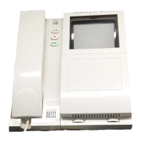
901/MV Videophone with memory board Videocitofono con memoria video
See at page 19 Vedere pag. 19
n..
521 Additional power supply Alimentatore supplementare
See at page 19 Vedere pag. 19
1
901 -M -F
901 Colour
Videophone Videocitofono n=user n=numero utentin...
890 Switchboard Centralino 1
850 Power transformer Trasformatore di alimentazione 1
852..-3 Front support Sostegno portamoduli See type and qty at page 11, 14
Per tipo e quantità vedere a pag. 11, 14
1+n..
830..
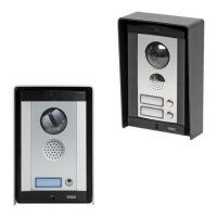
830.. colour
Camera module Modulo telecamera 1
837-0-1-2.. Speaker unit module Modulo portiere elettrico
843..-4..-5..
Extension front panel module Modulo di chiamata See type and qty at page 10, 14
Per tipo e quantità vedere a pag. 10, 14
n...
894 Video distribution box Distributore video di piano As may be required
Q.tà da stabilire in base alle esigenze
n...
CM10 Multicore cable -9+coax Cavo 9 fili + coax
Between control unit and videophone Per collegamento centralino-videocit.
mt.
CM13 Multicore cable-12+coax Cavo 12 fili + coax
Between control unit and
outdoor
station
Per collegamento centralino-posto est.
mt.