11
5. Programmierung
BevorSiemitdemProgrammierendesLokdeco-
ders beginnen, muss der Motor an den Decoder
angeschlossen sein, da sonst keine Rückmeldung
zur(DCC)Zentraleerfolgenkann.
Wenn Sie den Decoder mit einer Motorola-Zentra-
le programmieren wollen, sollten Sie an die Aus-
gänge AUX1 und AUX2 Beleuchtungen anschlie-
ßen, da die Lok den Wechsel in den Programmier-
modus und die Übernahme der Eingaben durch
das Blinken der Beleuchtung an diesen Ausgän-
gen quittiert.
ImDCC-FormatkönnenSiedieseKongurati-
onsvariablen(CVs)programmieren.Die„Haupt-
gleisprogrammierung“(POM)istebenfallsmög-
lich. Im Motorola-Format werden die Einstellungen
in sogenannte Register programmiert, die Zähl-
weiseistmitderderCVsidentisch.
Programmierung mit DCC-Zentralen
VonderZentraleauskönnenSiedieKongurati-
onsvariablen(CVs)desDecodersprogrammieren.
Beachten Sie dazu den betreffenden Abschnitt in
der Bedienungsanleitung Ihrer Zentrale, in der die
byteweiseProgrammierungderCV-Variablenbe-
schrieben ist.
5. Programming
Before starting the programming you should con-
nect the motor to the decoder in order to assure
thenecessaryfeedbackfromthedecodertothe
(DCC)commandstation.
Should you intend to program the decoder with a
Motorola central unit you should always connect
thelightingtotheoutputsAUX1andAUX2.The
locomotiveconrmsthechangeintotheprogram-
ming mode and the acceptance of programming
commandsbyashingthelights.
InDCCformatyoucanprogramtheconguration
variables(CVs).Thiscanalsobedoneby“Pro-
grammingontheMain”(POM).
IntheMotorolaformatthesettingsaresavedin
so called registers. The method of counting is the
sameaswiththeCVs.
Programming with a DCC command
station
Youcanprogramthecongurationvariables
(CVs)ofthedecoderfromthecommandstation.
Alsotakenoteoftherelevantchapteroftheman-
ual of your command station where the byte-wise
programmingof(CVs)isexplained.
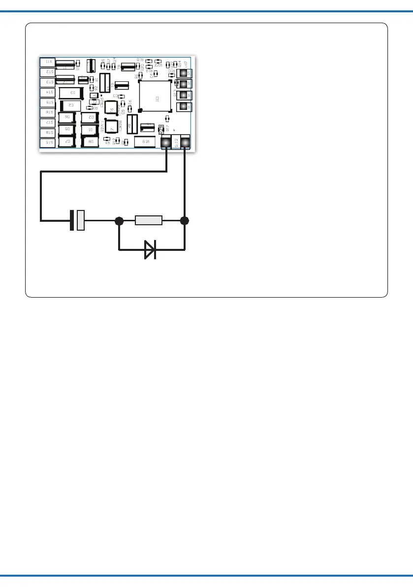
Bei Werten bis zu 10 Ohm kann je nach
Motortyp evt. auf die Diode verzichtet werden.
For resistor ratings of up to 10 Ohms and subject
to the motor type the diode may be omitted.
Elko -
+
SUSI DATA
SUSI CLOCK
SUSI PLUS
SUSI GROUND
Diode
Elektrolytkondensator
Electrolytic Capacitor
Widerstand / Resistor
10 ... 100 Ohm 0,5 W
Type 0207 oder 0411
Typ 1N4001 o. ä.
oder B160; Gl 10
100 - 470 µF /
>25 V
Fig. 4
Abb. 4
Anschluss von SUSI-Modulen / Wiring SUSI modules