8
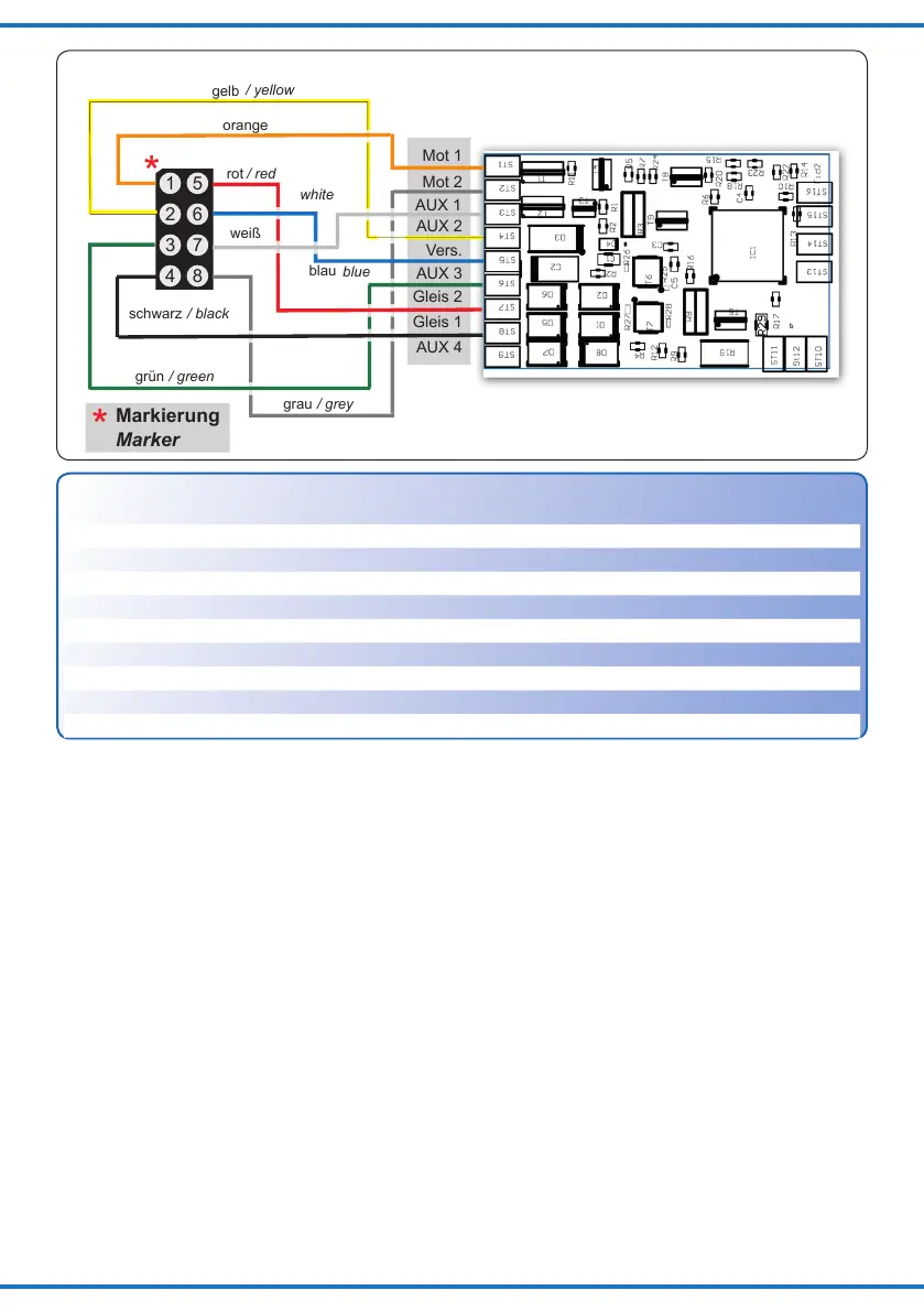
1
2
3
4
5
6
7
8
*
rot
schwarz
blau
Markierung
orange
gelb
weiß
Mot 1
Mot 2
AUX 2
Vers.
AUX 3
Gleis 2
Gleis 1
AUX 4
grün
AUX 1
/ red
/ black
blue
Marker
/ yellow
white
/ green
grau
/ grey
*
Fig. 3
Abb. 3
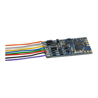
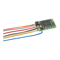
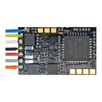
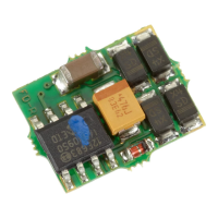
Decoder 5244: Einbau in Loks ohne NEM
652-Schnittstelle
Zum Einbau in Loks ohne Schnittstellenbuchse
verwendenSiebittedenDecodermitAnschluss-
drähten(Art.Nr.5244).BeachtenSieunbedingt
dieBelegungderAnschlüsse(Tabelleoben)und
die Abbildung 3.
►TrennenSiedieVerbindungendesMotorszu
denStromabnehmern(Radkontakte)bzw.bei
LoksmitelektronischemUmschalterdieVer-
bindungen des Umschalters zum Motor und zu
dem Schleifer bzw. zu den Radkontakten. Der
Umschalter wird nicht mehr benötigt und sollte
entfernt werden.
►LötenSiedievondenRadkontaktenkommen-
den Anschlüsse an den Kabeln „Gleis1“ und
„Gleis 2“ an.
►LötenSiedanndievomMotorkommenden
Anschlüsse an den Punkten „Mot 1“ und „Mot
2“ an. Sollte die Fahrtrichtung der Lok im Ana-
logbetrieb nicht mit der am Trafo eingestellten
Fahrtrichtung übereinstimmen, müssen Sie die
Decoder 5244: Installation in
locomotives without NEM 652 socket
Please use the decoder 5244 with wire harness
butwithoutplugforinstallationinlocomotives
withoutNEMsocket.
Observethecontactcongurationasperthetable
below and Figure 3.
►Disconnectthemotorfromthewheelpick-ups
orthechange-of-directionrelayrespectivelythe
wires from the electronic relay to the motor and
tothecentrepick-uporwheelcontacts.There-
layisnolongerneedandshouldberemoved.
►Solderthewirescomingfromthewheelcon-
tactstothepads“Gleis1”and“Gleis2”(Track1
andtrack2).
►Nextsolderthewiresfromthemotorto
thepoints“Mot1”and“Mot2”.Shouldthe
locomotive´sdirectioninanaloguemodenot
matchthedirectionoftravelofyourtransform-
eryoushouldswapthewireson“Gleis1”and
“Gleis2”.
Anschluss
Connector
Farbe Funktion
Colour Function
AUX 1 weiß Spitzenlicht(max.500mA) White Forwardheadlight(max.500mA)
AUX 2 gelb Schlusslicht(max.500mA) Yellow Rearlight(max.500mA)
AUX 3 grün Zusatzfunktion(max.500mA) Green Auxiliaryfunction(max.500mA)
AUX 4 Lötpad Zusatzfunktion(max.500mA) Soldering pad Auxiliaryfunction(max.500mA)
Vers. blau gemeinsamer Rückleiter Blue Common return
Gleis 2 schwarz Radstromkontakt rechts Black Righttrackconnection
Gleis 1 rot Radstromkontakt links Red Lefttrackconnection
Mot 2 grau Motorausgang(bis1A) Grey Motor(max.1A)
Mot 1 orange Motorausgang(bis1A) Orange Motor(max.1A)
Anschlussschema / Wiring connections