5
Installation and connections
Electrical connections
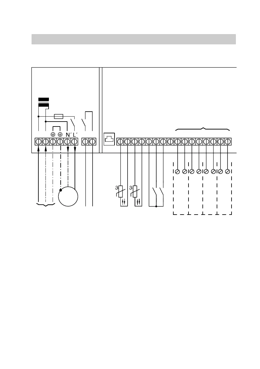
Connection and wiring diagram
A Cascade control unit
B Mains connection 230ĂV~ă50ĂHz
C Distribution pump
D Fault message (zero volt)
E Separator (as delivered condition)
F Viessmann 2ĆwireĂBUS for
connection to VitotronicĂ050,
VitotronicĂ050 accessory
G Outside temperature sensor
H Flow temperature sensor
K Party key
L External demand
M KM BUS interface
to VitodensĂ200
KĂ1 to KĂ4 Connection for
boilers 1 to 4
Sensors
Install sensors in their appropriate
positions and connect in accordance
with the diagram.
External switching contacts
Connect the external switching
contacts, the party key and the
"External demand" switching
contact (if installed) in accordance
with the diagram.
Boiler
Connect via the KM BUS interface in
accordance with the diagram.
5862Ă474ĂGB
1817
X5.4
X5.3
FT4A
X5.4
X5.3
X5.3
X5.4
X5.3
X5.4
16151413121110987654321
NL
1 ~
M
B
D
C
GHKL
M
K
F
K1
K2
K3
K4
EA
K