10
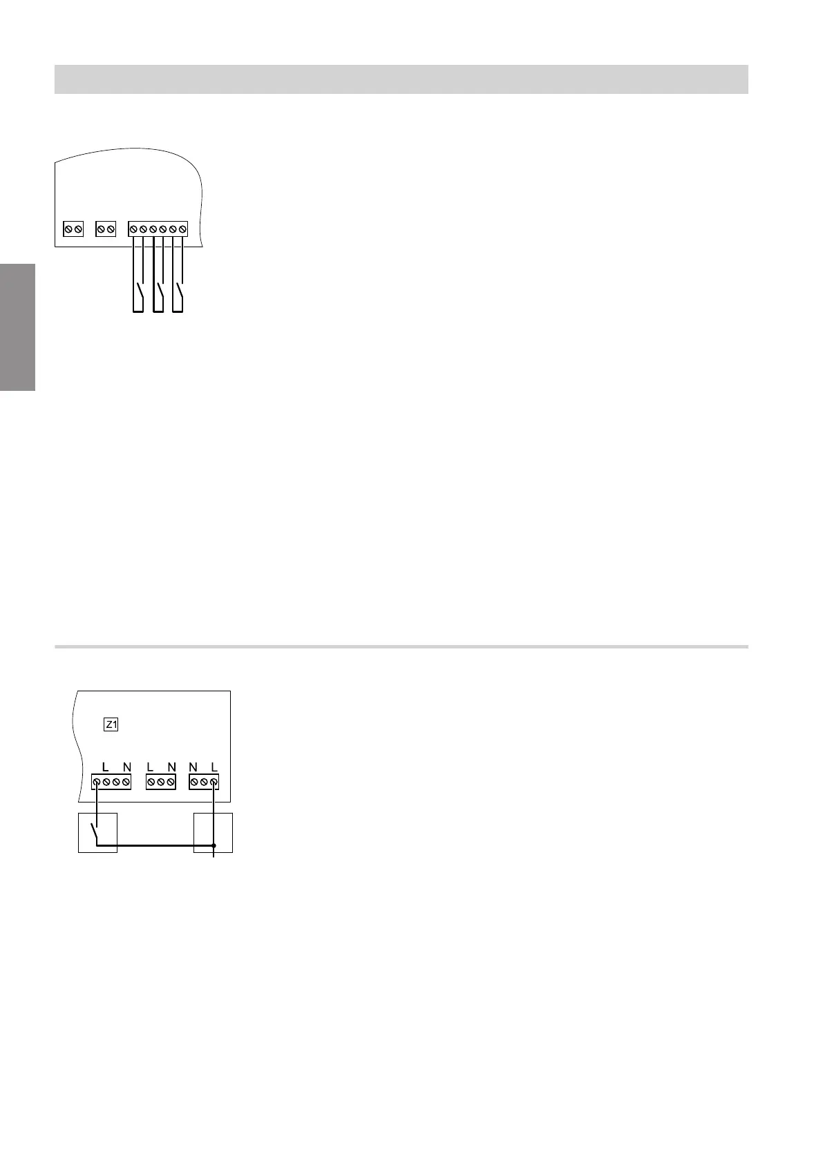
Connecting the operating mode changeover: DI1 to DI3
jF jF
[{][{][{]
DI1 DI2 DI3
1
2
3
4
1
2
3
4
5
6
Fig. 5
■
External contacts at DI1, DI2 and DI3 must be poten-
tial-free.
■
When making the connection, adhere to the require-
ments of protection class II. That is 5.0 mm air and
creep paths and 2.0 mm insulation thickness against
'live' components.
Weather-compensated operation
As soon as the contact closes, the following demand
becomes active:
■
Demand for all installed heating circuits simultane-
ously, with the respective programmed set room tem-
perature of the individual heating circuit:
DI1 Reduced room temperature
DI2 Standard room temperature
DI3 Comfort temperature
Continuous operation or room temperature-
dependent operation
As soon as the contact closes, the following demands
become active:
■
Set flow temperature demand for the system
■
Demand for all installed heating circuits simultane-
ously, at the respective programmed temperature
level of the individual heating circuit:
DI1 Reduced flow temperature
DI2 Standard flow temperature
DI3 Comfort flow temperature
(Only with continuous operation)
Connecting external demand: fD
Fig. 6
A
Signal for external demand or external blocking
B
Junction box
The demand is active if 230 V voltage is present at dig-
ital input 43-1. A demand is issued to the heat genera-
tor.
The set values for the flow temperature and the speed
of the primary pump are specified with parameters
528.0 and 1100.2.
Installation sequence
Connecting external functions (cont.)
6131087
Installation