7
Fig. 1
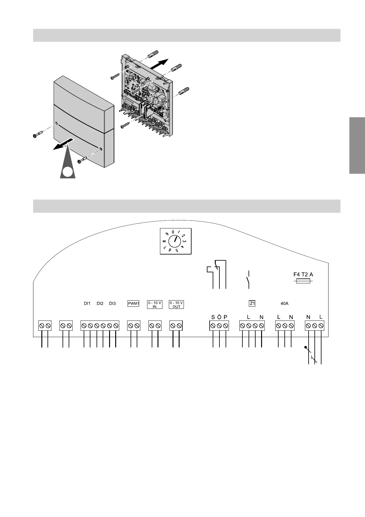
Overview of electrical connections
jF jF
[{][{][{]
hH
[{]
fÖ
1
2
3
4
1
2
3
4
5
6
1
2
1
2
1
2
?
1
?
?
fD
K1
S1
+
-
+
-
Fig. 2
DI1 Digital input 1
DI2 Digital input 2
DI3 Digital input 3
0 - 10 V IN 0 - 10 V input
0 - 10 V OUT 0 - 10 V output
F4 Fuse 2 A (slow)
PWM1 Control voltage output
S1 Rotary switch for subscriber number
addressing
Z1
fD
230 V relay output, 230 V input
fÖ
Power supply
fÖ
A
Power supply for additional accessories
hH
Changeover contact (floating switching
contact) for connecting signalling equip-
ment for fault messages or an extractor
hood
jF
PlusBus
Installation sequence
Wall mounting
6131087
Installation