13
■
External contacts at DI1 must be potential-free.
When making the connection, adhere to the require-
ments of protection class II. That is 5.0 mm air and
creep paths and 2.0 mm insulation thickness against
'live' components.
■
Rated current at fault message output
hH
:
Max. 1 A ~.
The fault messaging is active if the digital fault mes-
sage input DI1 is closed. The heat generator is
blocked.
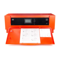
Floating fault message output
hH
is switched over from
"Ö" to "S". Fault message F.104 is shown.
Connecting only message facility: hH
Example: Buzzer with illuminated signal switched in
parallel
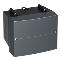
Fig. 11
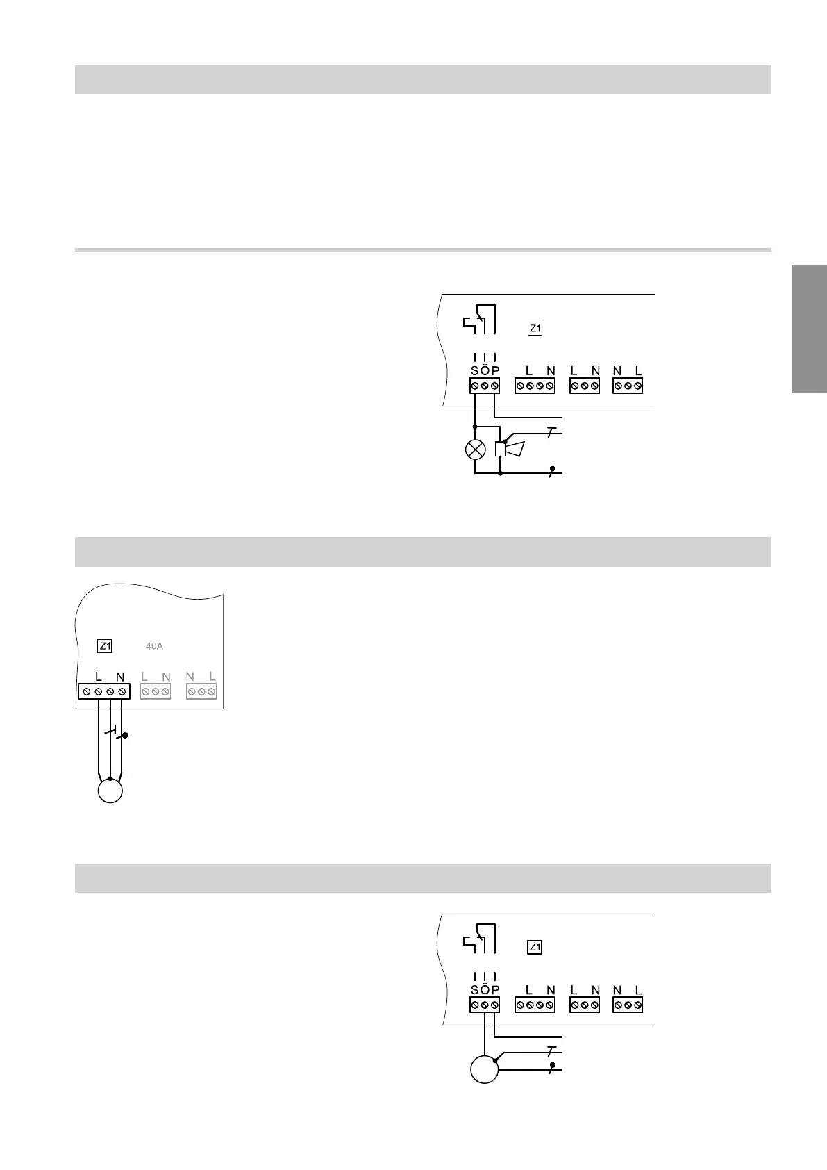
Connecting the external LPG valve: fD
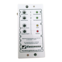
Fig. 12
Output 43-L is active as soon as the burner control unit
starts the burner. The external LPG valve opens.
Connecting the external extractor interlock: hH
Example: Extractor hood
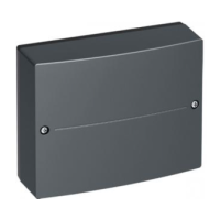
Fig. 13
Installation sequence
Connecting the fault message input and fault… (cont.)
6131087
Installation