9
hH
[{]
fÖ
1
2
1
2
?
1
?
?
fD
+
-
+
-
U
+
A
B
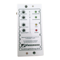
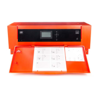
Fig. 3
A
Enable signal
B
Junction box
When making the connection, ensure correct polarity
of the DC control voltage 0 - 10 V.
Note
No galvanic separation is required between the earth
conductor and the negative pole of the on-site power
source.
The 0 to 10 V hook-up generates the following set flow
temperatures:
< 1 V No default set flow temperature
1 V ≙ 10 °C
10 V ≙ 100 °C or max. set flow temperature in
accordance with factory-set limit for heat gener-
ator
If 230 V voltage is present at digital input 43-1, the
external default set flow temperature is enabled.
Connecting an external default output: 0 - 10 V IN
Analogue input for connecting the external default set
flow temperature or the external default output
hH
[{]
fÖ
1
2
1
2
?
1
?
?
fD
+
-
+
-
U
+
A
B
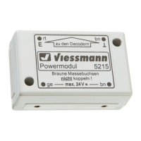
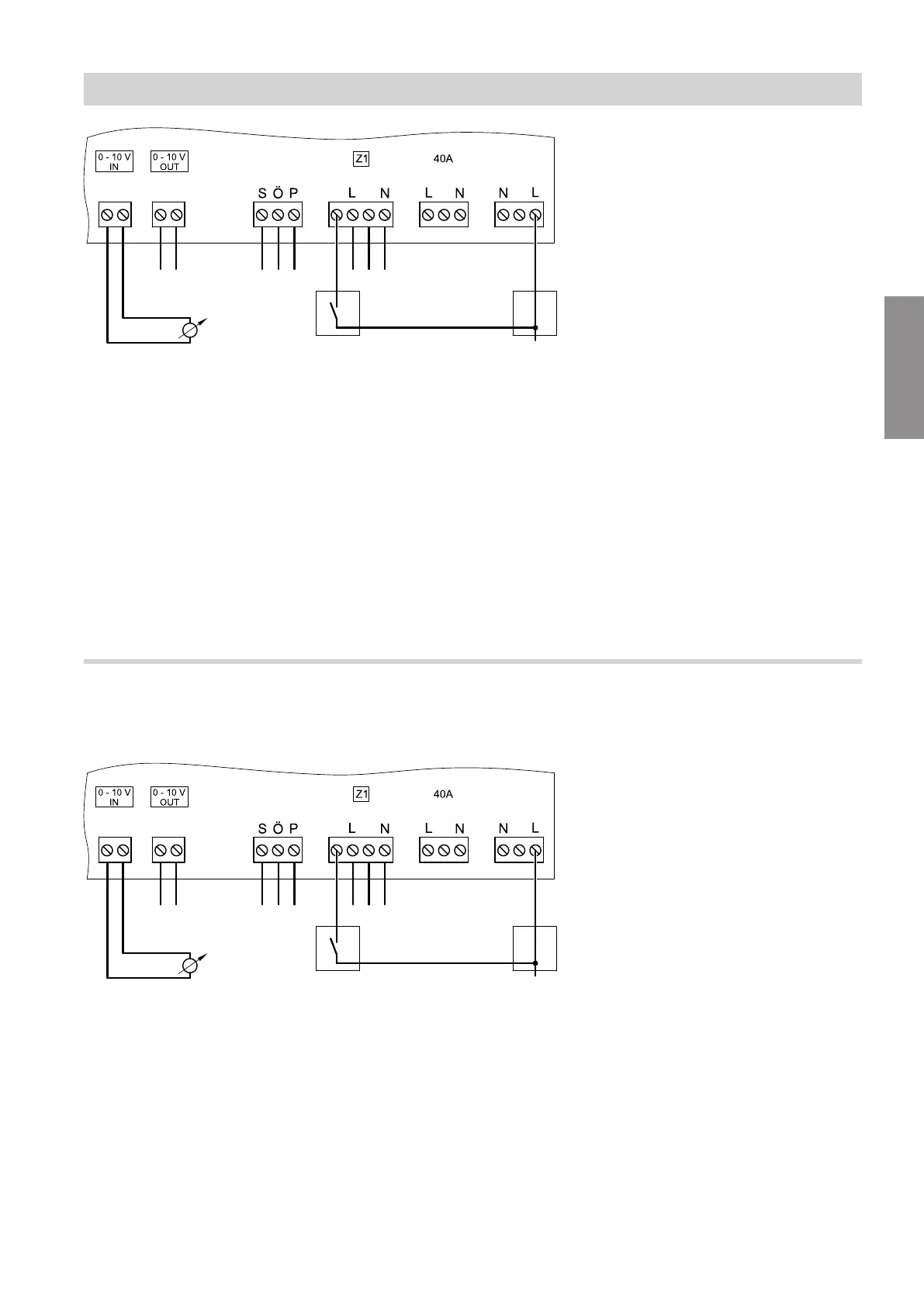
Fig. 4
A
Enable signal
B
Junction box
When making the connection, ensure correct polarity
of the DC control voltage 0 - 10 V.
Note
No galvanic separation is required between the earth
conductor and the negative pole of the on-site power
source.
The 0 to 10 V hook-up generates the following default
output for the heat generator:
< 1 V ≙ 0 %
1 V ≙ 10 % or lower modulation limit
10 V ≙ 100 %
If 230 V voltage is present at digital input 43-1, the
external default output is enabled.
Installation sequence
Connecting external functions (cont.)
6131087
Installation