8
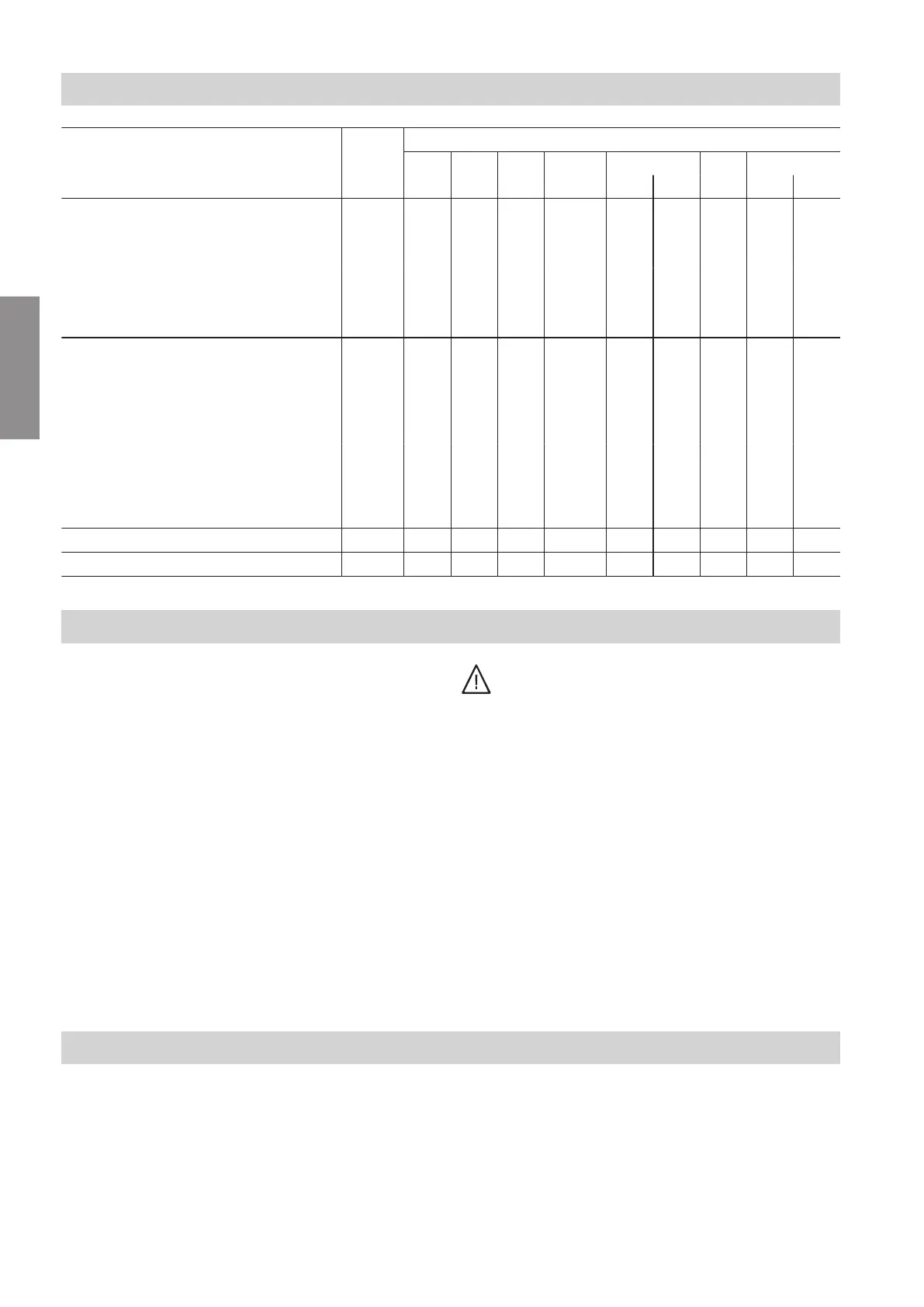
Function Page Connections:
DI1 DI2 DI3 PWM1 0 - 10 V
hH fD
IN OUT 43-1 43-L
External functions
■
External default set flow temperature 8 X X
■
External default output 9 X X
■
Operating mode changeover 10 X X X
■
External demand 10 X
■
External blocking 11 X
Fault message input and fault mes-
sage output
■
Connection without system blocking 11 X X
■
Connection with system blocking,
230 V
12 X X
■
Connection with system blocking,
24 V
13 X X
■
Connecting only message facility (e.g.
buzzer)
13 X
External LPG valve 13 X
External extractor interlock 13 X
Electrical connections
!
Please note
Electronic assemblies can be damaged by elec-
trostatic discharge.
Prior to commencing any work, touch earthed
objects such as heating or water pipes to dis-
charge static loads.
■
Apply strain relief to on-site cables.
■
Seal any unnecessary apertures with cable grom-
mets (not cut open).
Danger
Incorrect wiring can lead to serious injury from
electrical current and result in appliance dam-
age.
Take the following measures to prevent wires
drifting into the adjacent voltage area:
■
Route extra low voltage (ELV) leads < 42 V
separately from cables > 42 V/230 V~/400 V~.
Secure with cable ties.
■
Strip as little of the insulation as possible,
directly before the terminals. Bundle the
cables close to the corresponding terminals.
■
If 2 components are connected to the same
terminal, press both cores together in a single
wire ferrule.
■
When connecting external switching contacts
and on-site components, observe the insula-
tion requirements of IEC/EN 60335-1.
Connecting external functions
Connecting external default set flow temperature: 0 - 10 V IN
Analogue input for connecting the external default set
flow temperature or the external default output
Installation sequence
Overview of electrical connections (cont.)
6131087
Installation