15
■
Connect all pipework with detachable fittings.
■
Seal any connections that are not required with red
brass caps.
■
Adjust the temperature controller and high limit
safety cut-out so that the DHW temperature in the
DHW cylinder does not exceed 95 °C.
Individual cylinder Cylinder bank with Viessmann header
Permissible heating water flow tempera-
ture
160 °C 120 °C 160 °C
Permissible operating pressure
■
Heating water side 25 bar
2.5 MPa
18 bar
1.8 MPa
16 bar
1.6 MPa
■
DHW side 10 bar
1 MPa
10 bar
1 MPa
10 bar
1 MPa
Test pressure
■
Heating water side 40 bar
4 MPa
■
DHW side 16 bar
1.6 MPa
Permissible DHW temperature 95 °C
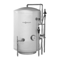
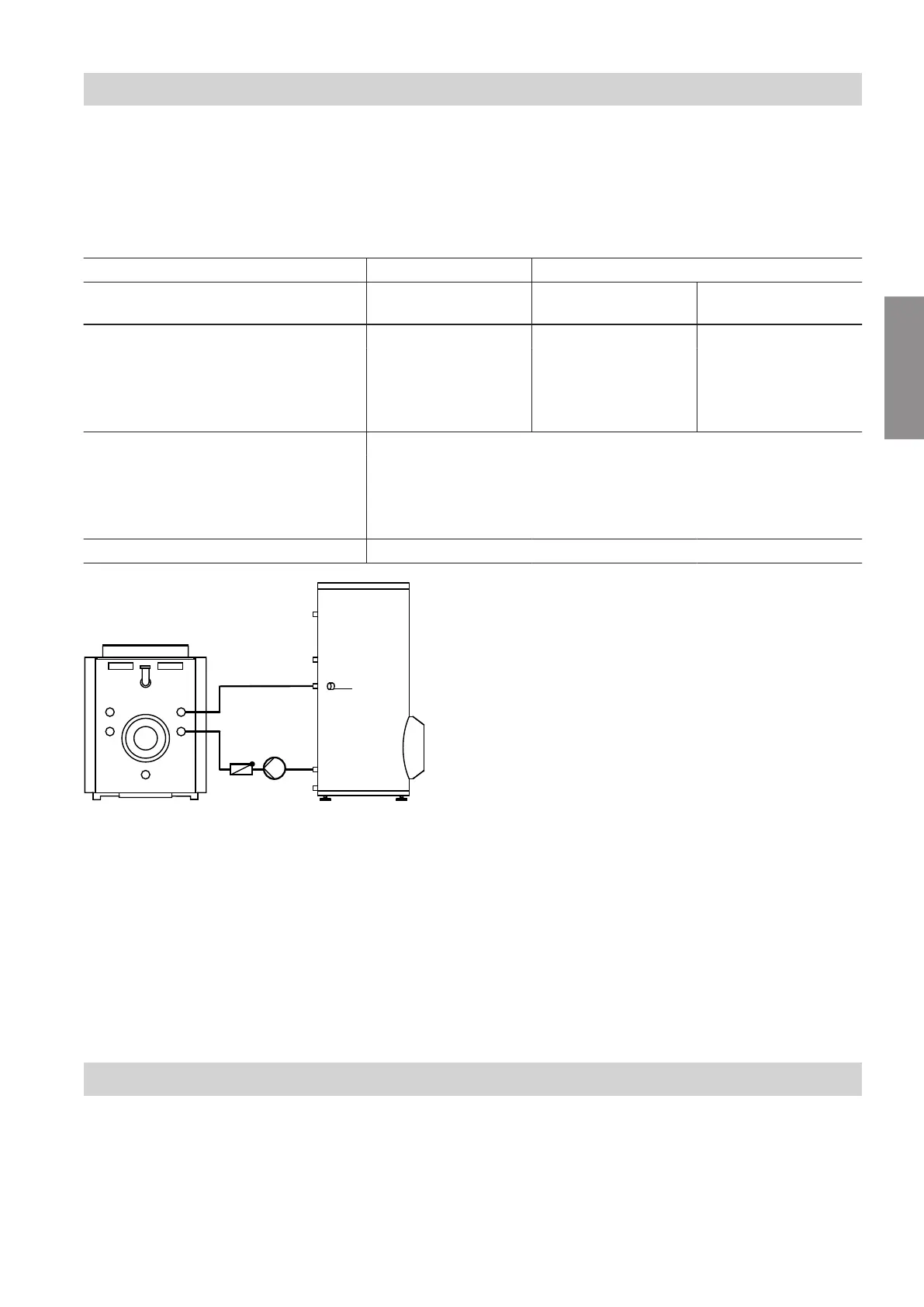
Fig. 12
HR Heating water return
HV Heating water flow
RV Spring-loaded check valve
STS Cylinder temperature sensor or temperature con-
troller and high limit safety cut-out (if required).
UP Circulation pump
1. For heating water flow temperatures in excess of
95 °C and cylinder capacity from 160 to 300 l:
Remove the pipe collars from the pipe outlets on
the heating water side.
Note
Pipe collars have l.h. threads.
2. Install the heat supply control unit.
Note
One temperature controller in one of the cylinders
is sufficient for cylinder banks. A water temperature
controller may also be used instead of the temper-
ature controller.
3. Install the flow line with a rise and fit an air vent
valve at the highest point.
4. Only for heating water flow temperatures above
110 °C: If the system does not already have one,
also install a type-tested high limit safety cut-out.
For this, use a temperature limiter and high limit
safety cut-out (TR/STB).
Connections on the DHW side
■
For connections on the DHW side, observe
DIN 1988 and DIN 4753.
■
Connect all pipework with detachable fittings.
■
Seal any connections that are not required with red
brass caps.
■
Equip the DHW circulation pipe with a DHW circula-
tion pump, check valve and time switch.
■
Connect the DHW circulation pump either to the
boiler control unit or via a time switch.
Installation sequence
Connections on the heating water side
6150608
Installation