2. Insert a new LE nozzle E (whilst
holding the oil preheater).
Select the nozzle in accordance
with the details on page 13.
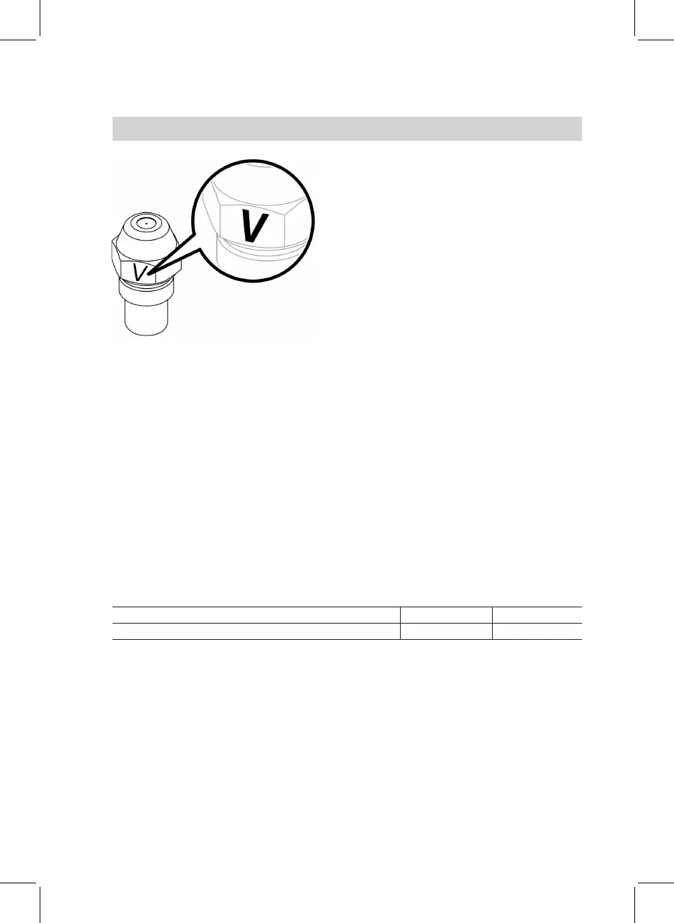
!
Please note
Only use nozzles marked
"V" (on the hexagon) (see
Fig.).
3. Insert rifling facility D as far as
possible. Align ignition electrodes
B in accordance with the drilled
holes towards the cable entries.
Install the oil burner nozzle cen-
trally in the restrictor.
4. Secure Allen screw C of the rifling
facility. Check nozzle gap "a".
!
Please note
An incorrectly adjusted noz-
zle gap "a" can result in irre-
gular operation of the burner
and even a fault shutdown.
Rated output kW 12.9/19.3 16.1/23.5
Nozzle gap "a" (see page 18) mm 3.0
+0.2/-0.3
1.5
+0.2/-0.3
Further details regarding the individual steps (cont.)
19
Initial start-up, inspection, maintenance
5692 536 GB