Do you have a question about the Viessmann VITOPLEX 300 Type TX3A and is the answer not in the manual?
Low temperature oil/gas boiler with modulating boiler water temperature.
Details operating conditions for boilers with specific control units.
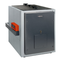
Description of low temperature oil/gas boiler for higher outputs.
Operating conditions for boilers with specific control units.
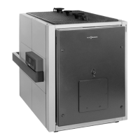
Low temperature oil/gas boiler with multi-layered convection heating surfaces.
Details operating conditions for boilers with specific control units.
Low temperature oil/gas boiler with multi-layered convection heating surfaces.
Details operating conditions for boilers with specific control units.
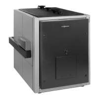
Low temperature boiler with oil/gas condensing heat exchanger.
Details operating conditions for boilers with specific control units.
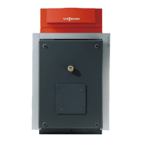
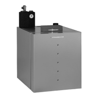
Low temperature oil/gas boiler with cast iron sectional design.
Details operating conditions for boilers with specific control units.
Low temperature oil/gas boiler in individual cast iron sections.
Details operating conditions for boilers with specific control units.
Specifications for Vitoflame 100 pressure-jet oil burners.
Specifications for Vitoflame 100 pressure-jet gas burners.
Illustrations of burner components and their identification.
Continuation of Vitoflame 100 gas burner specifications.
Additional diagrams of burner components and connections.
Specification of accessories for heating circuits.
Details on the wall-mounted Divicon heating circuit distributor.
Diagrams and specifications for heating circuit connections.
Performance curves for DN 25, 32, 40, 50 heating circuit pumps.
Details on Grundfos heating circuit pumps and motor protection.
Performance curves for heating circuit pumps DN 25/32, 40, 50.
Wiring diagrams for heating circuit pumps and control units.
Diagrams showing pressure drop for boiler circuits and mixers.
Information on delivery, handling, and installation of the boiler.
Guidelines for system design, including flow temperatures and safety.
Details on water connections, boiler circuits, and shunt pumps.
Details on safety equipment required for hot water heating systems.
Table listing required control equipment for sealed heating systems.
Information on suitable burners and their installation.
Requirements for flue gas routing and German combustion order.
Guidelines for calculating flue gas system cross-sections.
Diagrams for calculating flue gas parameters.
Diagram for sizing round flue gas system cross-sections.
Diagram for sizing square flue gas system cross-sections.
Requirements for flue systems of condensing boilers.
Information on flue gas temperature sensors and their installation.
Options for installing flue systems for the Vitoradial 300-T.
Minimum distances for ventilation between duct and female connection.
CE certificate for PPs flue gas systems for the Vitoradial 300-T.
Requirements for open flue operation with the Vitoradial 300-T.
List and specifications of individual plastic flue system components.
Dimensions and specifications for support bends.
Information on support rails for flue systems.
Specifications for duct covers used in flue systems.
Dimensions for spacers used in flue systems.
Specifications for various lengths of plastic flue pipes.
Dimensions for plain inspection pieces in flue systems.
Dimensions for simple 87° bends in flue systems.
Dimensions for simple 45° bends in flue systems.
Specifications for ventilation bezels used in flue systems.
Dimensions for inspection bends in flue systems.
Information on ordering boiler flue connections.
Instructions for connecting PPs flue pipes to MR chimneys.
Measures to reduce airborne noise from boilers and heating systems.
Measures to reduce structure-borne noise and vibrations.
Water quality requirements for systems up to 100°C.
Water quality requirements for systems with flow temperatures over 100°C.
Guidelines and considerations for using antifreeze in boiler systems.
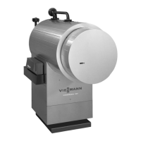
Information on the Vitotrans 300 flue gas/water heat exchanger.
Details on energy savings achieved with the Vitotrans 300.
Method for calculating possible energy savings with the Vitotrans 300.
Information on the hydraulic connection of the Vitotrans 300.
Requirements for condensate and neutralisation for oil and gas boilers.
Overview of available boiler control units and their functions.
Overview of available boiler control units and their functions.
Details on control units for single boiler systems.
Description and functions of the Vitotronic 100, type GC1 control unit.
Description and functions of the Vitotronic 200, type GW1 control unit.
Description and functions of the Vitotronic 300, type GW2 control unit.
Information on control units for multi-boiler systems.
Role of Vitotronic 100, type GC1 in multi-boiler systems.
Description and functions of the Vitotronic 300-K, type MW1 control unit.
Vitotronic 300-K, type MW1 system control unit.
Diagram showing switching points based on outside temperature.
List of components included in the delivered control units.
Table mapping components to specific control unit types.
Specification and details for the boiler water temperature sensor.
Specification and details for the cylinder temperature sensor.
Specification and installation details for the outside temperature sensor.
Specification and construction of the Vitotronic 100, type GC1.
List of items included in the control unit delivery.
Options for heating systems with DHW cylinders.
Specification and construction of the Vitotronic 200, type GW1.
Description of available heating programs and frost protection.
How to adjust heating curves for optimal system performance.
Components included with the control unit delivery.
Separate ordering information for DHW cylinder systems.
Specification and construction of the Vitotronic 300, type GW2.
Description of heating programs and frost protection.
How to adjust heating curves for system flow temperature.
List of components delivered with the control unit.
Information on DHW cylinder systems and separate ordering.
Specification and construction of the Vitotronic 300-K, type MW1.
Description of heating programs and frost protection.
How to adjust heating curves for system flow temperature.
Table mapping accessories to different control unit types.
Table mapping accessories to different control unit types.
Details and specifications for the extension kit for heating circuits.
Specification for flow temperature sensors.
Information on mixer motors for flanged mixers.
Part numbers and details for sensor plugs.
Specification for contact temperature sensors.
Specification for immersion temperature sensors.
Specification for immersion thermostats.
Specification for contact thermostats.
Description and functions of the Vitotrol 200 remote control.
Description and functions of the Vitotrol 300 remote control.
Specification for separate room temperature sensors.
Specification for flue gas temperature sensors.
Information on radio clock receivers for time synchronization.
Adaptor for connecting external safety equipment to control units.
Specification for the 0-10 V function extension module.
How function extensions connect to control units.
Specification for cylinder temperature sensors.
Specification for sensor wells.
Specification for contactor relays.
Details on mating plugs for on-site burner connections.
Information on LON communication modules.
Specification for LON connecting cables.
Details on extending connecting cables for control units.
Information on LON bus terminator components.
Auxiliary functions for single boiler systems.
Auxiliary functions for single boiler systems.
Auxiliary functions for multi-boiler systems via LON.
Connecting on-site control units to Vitotronic 100 in single boiler systems.
Controlling boiler sequences with on-site cascade controllers.
Connecting on-site control equipment via the LON interface.
Overview of safety regulations and permit requirements.
Overview of safety regulations and permit requirements.
Requirements for gas installation.
Guidelines for pipe connections to the boiler.
Guidelines for electrical installation.
Requirements for system operating instructions.
Requirements for flue systems.
Information on the Energy Saving Ordinance (EnEV).
Information on the German Immissions Order (BlmSchV).
Building regulations approval process for combustion equipment.
| Fuel Type | Oil/Gas |
|---|---|
| Standard efficiency | 98% |
| Application | Commercial |
| Weight | Varies by model |
| Dimensions (HxWxD) | Varies by model |
| Water Pressure | Max 6 bar |
| Type | VITOPLEX 300 Type TX3A |
| Efficiency | Up to 98% |