Weather-compensated, digital cascade and heating circuit control unit:
■ Type MW1S: For installation in control panels (see separate data-
sheet).
■ For multi-boiler systems
■ With sequential boiler strategy
■ For up to two heating circuits with mixer (a further 32 Vitotronic 200-
H heating circuit control units can be connected via the LON).
An extension kit (accessory) is required for each heating circuit with
mixer
■ In conjunction with the Vitotronic 100, type GC1:
For two-stage or modulating burners, if installed
■ With cylinder thermostat
or
Control of a cylinder primary system with mixer assembly (only avail-
able as an alternative to the control of a constant return temperature
raising facility with a regulated three-way valve)
■ With boiler protection functions subject to system version:
– Distribution pump
or
– Shunt pump
or
– Control of a constant return temperature raising facility with a
regulated three-way valve (only available as an alternative to the
control of a cylinder primary system with mixer assembly)
■ With integral diagnostic system
■ Programming unit with plain text prompts
■ Via external contacts:
– Heating program changeover
– Requirement to default set flow temperature
– Blocking the burner
– Mixer "Open" or "Closed"
■ With capability to communicate via LON (LON communication mod-
ule and terminators are part of the standard delivery)
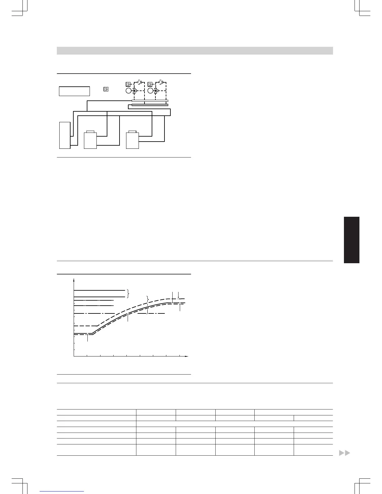
Switching points
A
Setting options for the high limit safety cut-out of the Vitotronic
boiler control units (delivered condition 110 ºC)
B
Setting options of the control thermostat of the Vitotronic boiler
control units (delivered condition 95 ºC)
C
Low-end boiler water temperature (see operating conditions
page 5 to 11)
D
Burner starting points
E
Burner shutdown points
F
Selected heating curve
G
Set maximum boiler water temperature
11.2 Components in the delivered condition
Allocation to control unit types
Vitotronic 100 200 300 300-K
Type GC1 GW1 GW2 MW1 MW1S
Components
Boiler water temperature sensor x x x
Cylinder temperature sensor x x x x
Outside temperature sensor x x x x
Contact temperature sensor (see acces-
sories)
x x
Control units
(cont.)
OIL/GAS BOILERS
VIESMANN
53
5822 426 GB
11