A
Burner stage 1 "ON"
B
Burner stage 2 "ON"
C
External load-dependent starting
A
,
B
and
C
are zero volt contacts of the higher control unit.
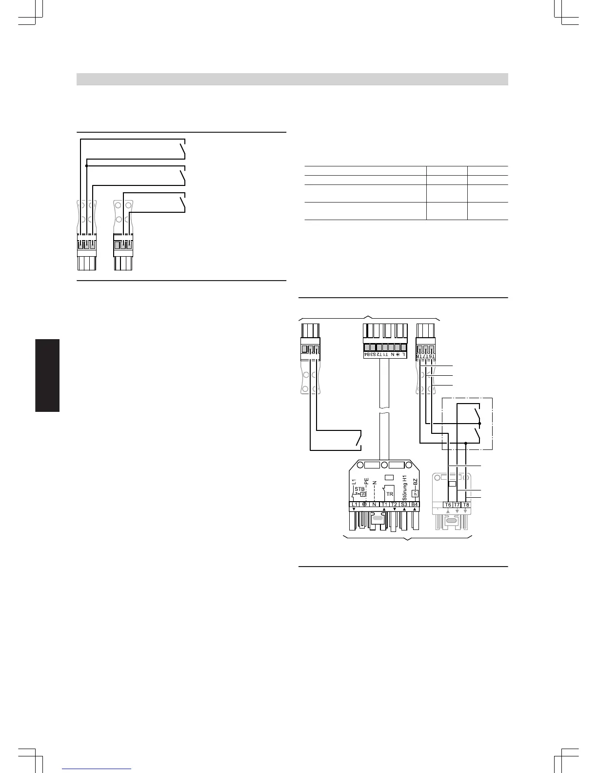
External burner start – burner stage 1
Contact at terminals 1 and 2 of plug
aVD
■ Contact closed:
Burner stage 1 is switched ON.
Burner stage 2 is switched ON only for maintaining the minimum
temperature.
The boiler water temperature is limited by the electronic maximum
temperature limiter (see the Vitotronic 100 service instructions), if it
is set below that of mechanical thermostat "
R
".
■ Contact open:
Burner stage 1 is switched OFF.
External burner start – burner stage 1 and 2
Contact at terminals 2 and 3 of plug
aVD
■ Contact closed:
Both burner stages are switched ON.
The boiler water temperature is limited by the electronic maximum
temperature limiter, if it is set below that of mechanical control ther-
mostat "
R
".
Burner stage 2 is switched OFF 2 K sooner.
■ Contact open:
Burner stages 1 and 2 are switched OFF.
External starting subject to load
The burner is started, subject to load, when the zero volt contact across
terminals "2" and "3" at plug-in connector
aVH
closes.
The boiler will be constantly operated at the set temperature.
The boiler water temperature is limited via the maximum set boiler
water temperature or via the mechanical control thermostat.
The set value is adjusted via code "9b".
Adjustments at the Vitotronic 100
■ Code "01:1" (delivered condition)
■ The boiler water temperature must be set to the lower value (see
operating conditions, pages 5 to 11).
The minimum boiler temperature is maintained (see operating con-
ditions, pages 5 to 11).
■ The cylinder thermostat is activated when the cylinder temperature
sensor is connected.
■ The high limit safety cut-out settings and other settings depend on
the system equipment level and the safety equipment to EN 12828
or EN 12953.
High limit safety cut-out 110 °C 100 °C
Temperature controller 100 °C 87 °C
Coding address "06" for electronic max-
imum temperature limit (Vitotronic 100)
95 °C 85 °C
Maximum temperature of the on-site
control unit
90 °C 80 °C
Note
A safety temperature of 120 °C (EN12953) is only permissible with
an additional, self-monitoring high limit safety cut-out. For an acces-
sory pack for safety temperature 120 ºC, see Viessmann pricelist.
Operation with a modulating burner