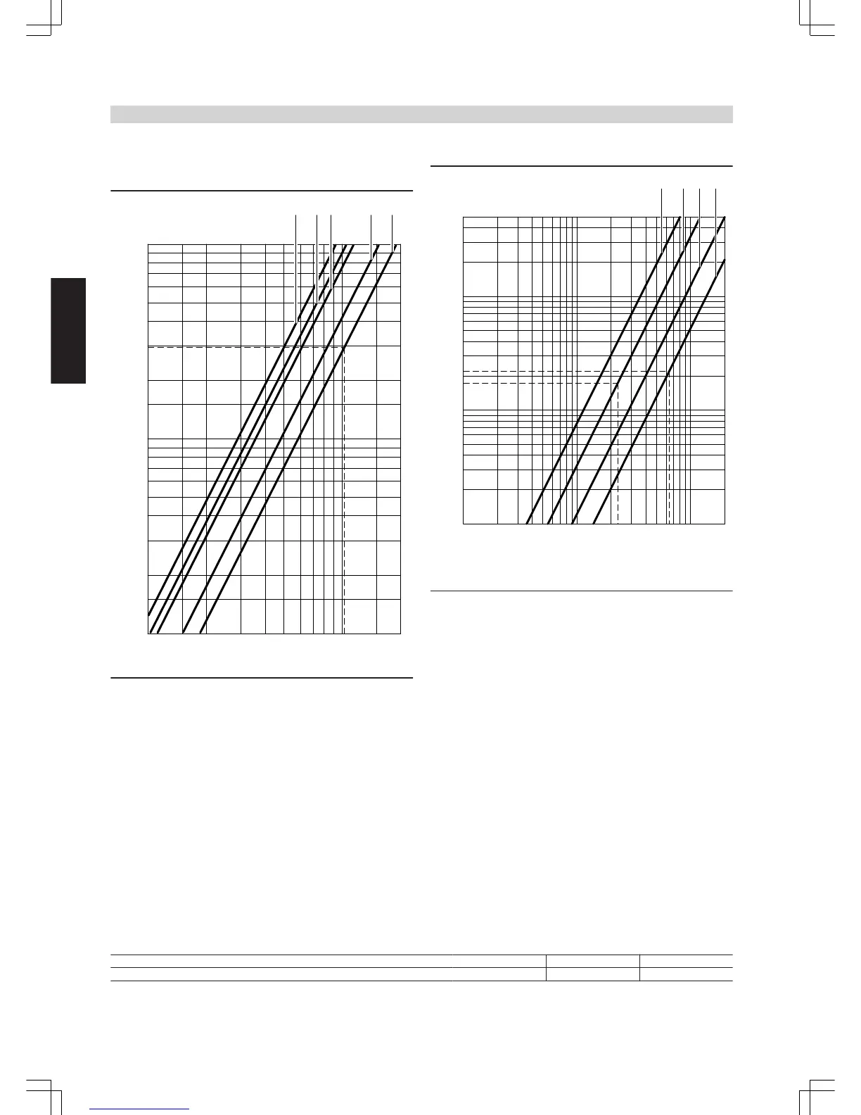
Boiler circuit pressure drop
(Boiler + pipework + flow distributor and return collector + heating cir-
cuit connection without mixer)
A
DN 65: Vitorond 200, 125 and 160 kW,
B
DN 65: Vitorond 200, 195 kW,
C
DN 65: Vitorond 200, 230 and 270 kW,
D
DN 65: Vitoplex 200/300, 90 to 200 kW
E
DN 80: Vitoplex 200/300, 235 to 300 kW
Mixer pressure drop
A
DN 25
B
DN 32
C
DN 40
D
DN 50
Note
For the resistances of the pipework between the boiler and distributor,
6 x 90° bends and 5 m pipe lengths should be taken into consideration.
If essentially different lengths and shapes must be used on-site, the
relevant drops in pressure must be calculated and taken into
account.
Example for calculating the residual head
Heating system with:
– Divicon heating circuit distributor DN 80
– Htg circ. 1: 1 heating circuit connection DN 25 without mixer, Output 35 kW,
Flow rate 1.5 m
3
/h
– Htg circ. 2: 1 heating circuit connection DN 32 with mixer, Output 60 kW,
Flow rate 2.5 m
3
/h
– Htg circ. 3: 1 heating circuit connection DN 50 with mixer, Output 150 kW,
Flow rate 6.5 m
3
/h
Total flow rate 10.5 m
3
/h
Boiler circuit pressure drop
Boiler + pipework + flow distributor and return collector + heating circuit connection (without mixer) (see diagram) = 30 mbar
Mixer pressure drop
(see diagram)
Mixer DN 32 50
Pressure drop mbar 18 22
Sum of the boiler circuit pressure drop and heating circuit connection pressure drop
Heating circuit 1: 30 mbar
Heating circuit 2: 30 mbar + 18 mbar = 48 mbar
Installation accessories
(cont.)
26
VIESMANN
OIL/GAS BOILERS
9
5822 426 GB