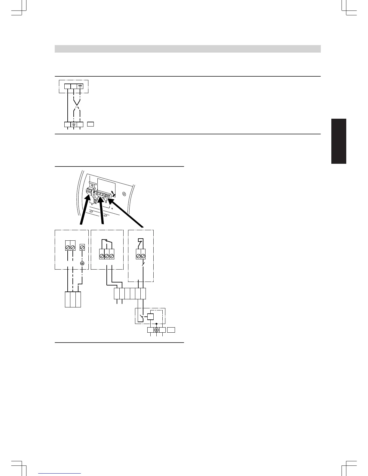
A
Power supply
B
Signal output
C
ON/OFF
D
Cable for starting/stopping a pump and pump fault notification (4-
core)
E
Central fault message
F
External starting/stopping of the pump
G
Connection via the contactor in the control panel or contactor
relay, part no. 7814 681
H Plug sÖ for connection to the Vitotronic
K
3-core cable for network connection to the pump
Colour coding to DIN IEC 60757
BK black
BK * black cable with imprint
BN brown
BU blue
GNYE green/yellow
Residual head
Residual head of the heating circuits
Deduct the pressure drop of the mixer and the boiler circuit (boiler,
pipework, flow distributor and return collector) from the pump head.
The total water volume of all heating circuits should be taken into con-
sideration in the boiler circuit.
Installation accessories
(cont.)
OIL/GAS BOILERS
VIESMANN
25
5822 426 GB
9