Burner
55
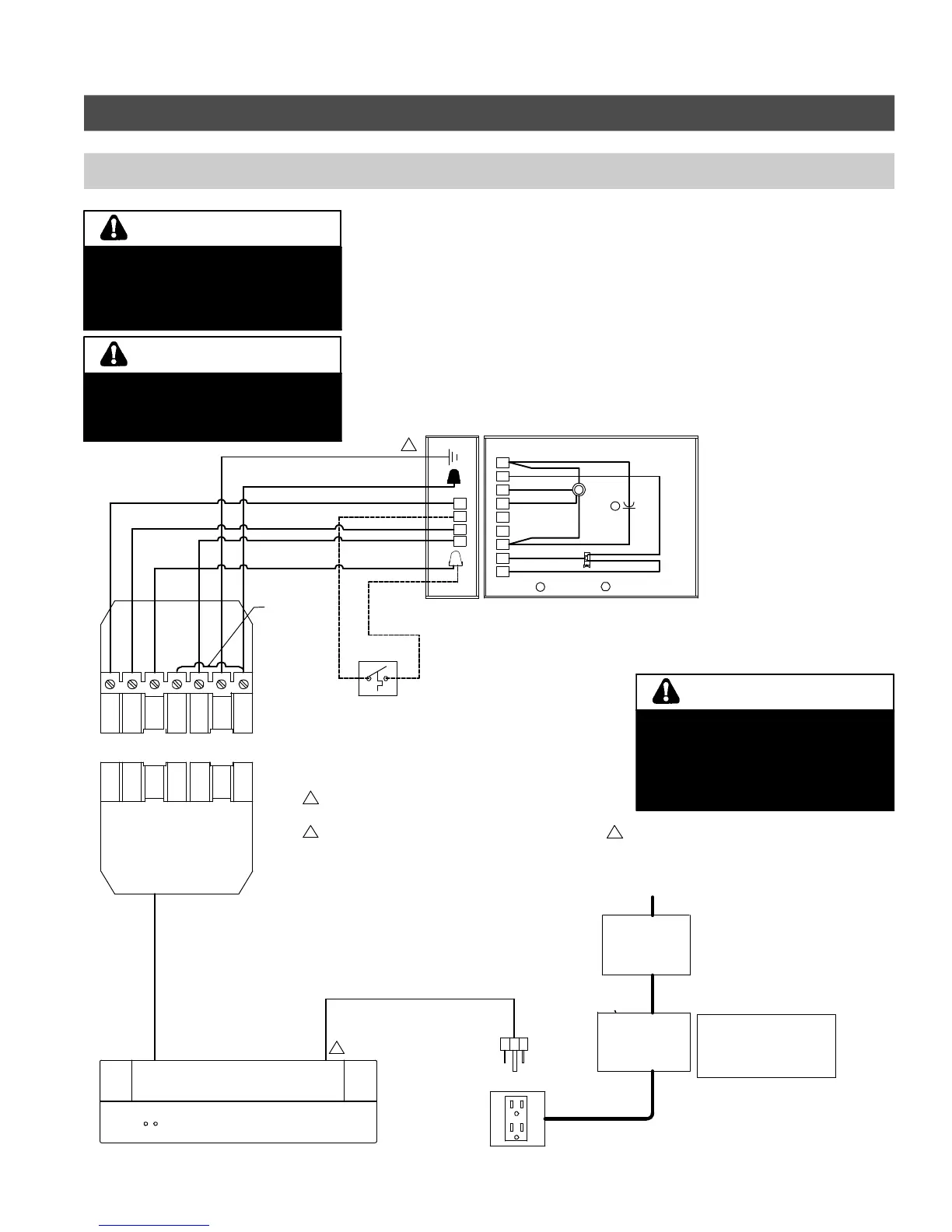
Burner Set-up (Riello) (continued)
Wiring diagram (with Vitotronic control)
Installations must follow these codes
and requirements:
- National Electrical Code, ANSI/NFPA
70, latest edition and any additional
national, state or local codes.
- In Canada, CSA C22.1 Canadian
Electrical Code Part 1 and any local
codes.
- Wiring must be N.E.C. Class 1. If
original wire as supplied with boiler
must be replaced, type 105°C wire
or equivalent must be used. Supply
wiring to boiler and additional control
wiring must be 14 ga. or heavier.
- Provide electrical ground at boiler as
required by codes.
5671 044 v1.0
Electric shock hazard. Can cause
severe personal injury or loss of life if
power source, including service
switch on boiler, is not disconnected
before installing or servicing.
WARNING
RED wire not used in this application.
DO NOT cut or remove closed end
connector from the wire.
(Live 120VAC at all times).
WARNING
L
N
.
9
8
7
6
5
4
3
2
1
W
BR
BK
W
BL
A
BK
BL
BK
BR
W
B
BK
WH
R
G
L1
R
G
T1
T2
WH
N
BK
S3
B4
BL
OG
G
L1
T1
T2
N
S3
B4
41
6
G
OG
BL
B
Capacitor
-
41
Factory
installed
jumper
Vitotronic Control (Refer to corresponding Vitotronic Control manual)
1
2
2
A
Motor
120 VAC receptacle
(field supplied)
120 VAC
power
supply
to boiler
Low water
cut-off
(if required)
(field supplied)
VIESMANN
Main
ON / OFF
switch
(field supplied)
120 VAC
Power supply
Installer must
provide 15A
overcurrent
protection
Refer to Vitotronic
200 / 300 (KW2 / KW3)
manual for alternate
connection location of
LWCO.
Blocked vent safety switch
(Canada only).
For installation in the United
States, connect BK (Black) wire di-
rectly to L terminal of the Riello
burner.
1
2
Power supply. Provide disconnect
means and overload protection as
required.
Control case must be connected
to earth ground.
Riello
burner
base
Riello factory wired
sub-base
Legend
Y Yellow
BL Blue
BK Black
OG Orange
WH White
G Green /
Ground
R Red
GY Gray
BR Brown
V Violet
Fig. 54
Ensure that the burner cycles ON and
OFF on proper call for heat before
leaving the job site. Failure to do so
may lead to boiler runaway situation,
which may lead to property damage,
personal injury or death.
WARNING