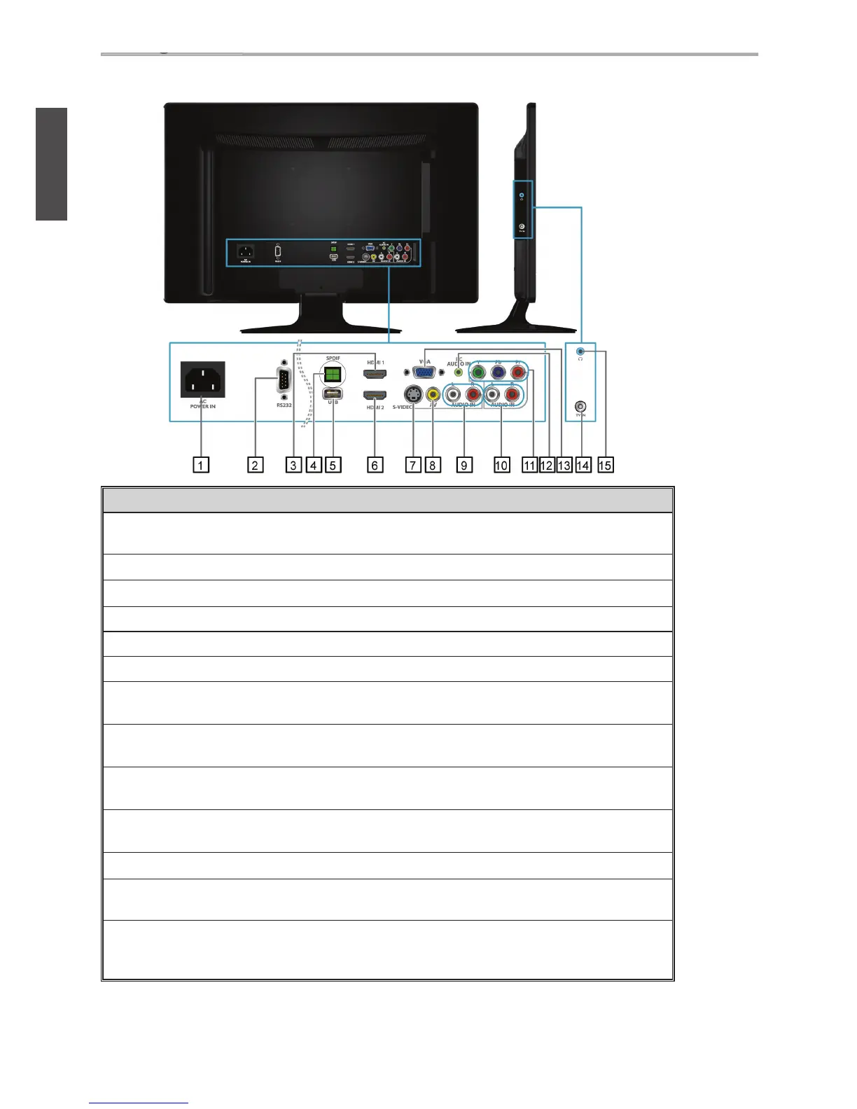
Rear View of the Product
Item Description
1 Power (AC input)
Plug-in the supplied AC Power cord and connect to the AC input
power source.
2
RS232 signal input
This port is for the service technician’s use.
3
HDMI 1 Input Terminal
Connect this port to the HDMI output of PC device.
4 SPDIF Optical output
Connect this port to the SPDIF input of A/V device.
5
USB
Connect to your USB devices, such as USB fl ash drive.
6
HDMI 2 Input Terminal
Connect this port to the HDMI output of A/V device.
7 S-Video input
Connect the S-Video cable from the compatible device to this
connector on the rear panel of the LCD TV.
8
Composite Video input
Connect this jack to the composite video output connectors on your
A/V equipment.
9
AV/ S-Video Audio
input (left/ right)
Connect the Audio in cable for AV/ S-Video from this jack to the
corresponding connectors on your A/V device.
10
YPbPr signal Audio
input (left/ right)
Connect the Audio in cable for YPbPr from this jack to the
corresponding connectors on your A/V device.
11
YPbPr signal input
Connect this port to the YPbPr output of A/V device.
12
PC Audio input
Connect the RGB Audio Out on your computer to the RGB Audio
on the rear of the LCD TV.
13
VGA signal input
Connect a 15-pin D-sub RGB cable to the RGB output of your
computer and the other end to the RGB input on the rear of the LCD
T V.