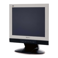
1. Outline
1.1 Power On/Off, 2Enter button (INPUT SELECT) , up arrow- button, down arrow button, 1MENU button,
button on the front panel.
1.2 D-sub 15pin connector, DVI-I connector and AC-IN jack are located on the back side of the cabinet.
1.3 OSD menu includes the following function;
Auto Image Adjust (only active under analog input)
Contrast/Brightness
Audio Adjust
Color Adjust
Information
Manual Image Adjust
Setup Menu
Memory Recall
1.4 Contrast and Brightness can be directly controlled with UP / DOWN key.
2. CONNECTORS
2.1 AC inlet : CEE22 typed connector
2.2 Video signal connector for analog input: 15P Mini D-Sub
PIN MNEMONI SIGNAL
1 RV Red Video
2 GV Green Video
3 BV Blue Video
4 NC None
5 GND Ground (DDC
return)
6 RG Red GND
7 GG Green GND
8 BG Blue GND
9 +5V +5V (for DDC)
10 SG Sync GND
11 NC None
12 SDA DDC Data
13 HS Horizontal Sync
14 VS Vertical Sync
15 SCL DDC Clock
CN6
DB15HD
1
6
2
7
3
8
4
9
5
11
12
13
14
15
10
16 17