Gasifying boiler VIGAS
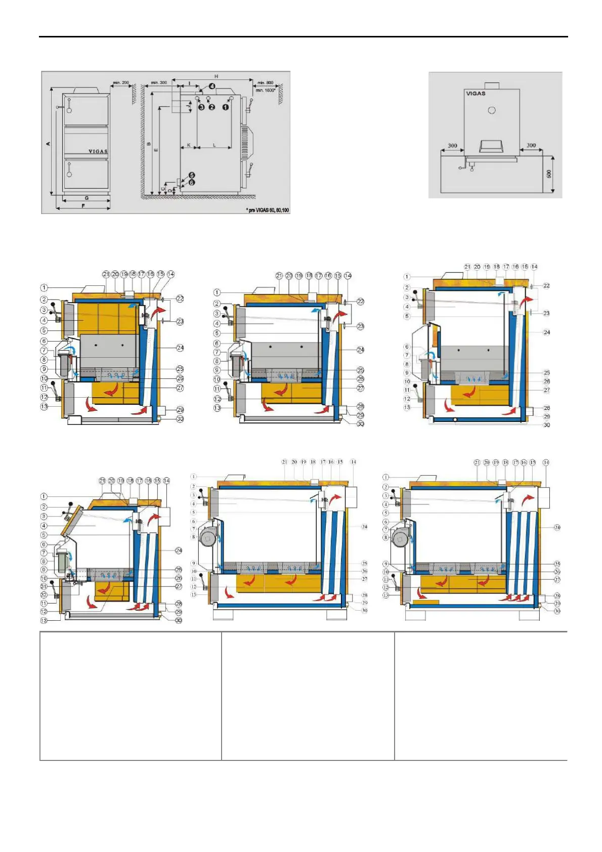
2.1 DIMENSION CHART AND THE POSITION OF SAFETY PLATE TO PROTECT EASILY
INFLAMMABLE FLOOR
2.2 BOILER SCHEMATICS
7
LEGEND
1. Control AK4000
2. Upper door
3. Chimney flap operating rod
4. Chamber area
5. Primary air conduction
6. Flap for servo Belimo
7. Fan
8. Fan cover
9. Nozzle
10. Secondary air flap
11. Handle
12. Fireclay bricks
13. Bottom door
14. Chimney output
15. Exchanger cover
16. Light up flap
17. Upper back panel
18. Water outlet
19. Thermal fuse
20. Thermometer
21. Upper front panel
22. Lambda sonda
23. Gases thermometer
24. Exchanger pipes
25. Heat proof/concrete filling
26. Secondary air
27. Combustion chamber
28. Gases direction
29. Reverse water leak
30. Filling leak
31. Cleaning flap for 29UD
32. Cleaning slot for 29UD
Schema VIGAS 60,80
Schema VIGAS 25 Schema VIGAS 40
Schema VIGAS 100
Schema VIGAS 16
Schema VIGAS 29 UD
Pic. 3
Inlet
brand for
drain
valve
Hole for drown valve insert
Outlet brand of cooling water