SECTION TSM 144.1 ISSUE B PAGE 3 OF 10
SPECIAL INFORMATION
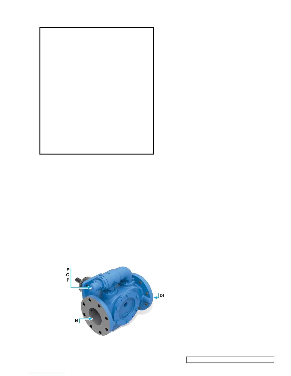
ROTATION: The KE –QS 4195 series are directional due
to the loading groove in the head. This series is designed
to operate in CLOCKWISE rotation only. Shaft rotation and
head design determines which port is suction and which is
discharge. Suction port is where pumping elements (gear
teeth) come out of mesh. An arrow on the head of the pump
indicates rotation and direction of flow.
PRESSURE RELIEF VALVES:
1. Viking pumps are positive displacement pumps and
must be provided with some sort of pressure protection.
This may be a relief valve mounted directly on the pump,
an inline pressure relief valve, a torque limiting device or
a rupture disk.
2. The relief valve adjusting screw cap must always point
towards the suction side of the pump. See Figure 2.
3. Pressure relief valves should not be used to control flow
or regulate discharge pressure.
FIGURE 2
RELIEF VALVE
ADJUSTING
SCREW CAP
SUCTION
DISCHARGE
DANGER !
Before opening any Viking pump liquid chamber
(pumping chamber, reservoir, relief valve
adjusting cap fitting, etc.) Be sure:
1. That any pressure in the chamber has been
completely vented through the suction or
discharge lines or other appropriate openings
or connections.
2. That the driving means (motor, turbine,
engine, etc.) has been “locked out” or made
non-operational so that it cannot be started
while work is being done on pump.
3. That you know what liquid the pump has been
handling and the precautions necessary to
safely handle the liquid. Obtain a material
safety data sheet (MSDS) for the liquid to be
sure these precautions are understood.
Failure to follow above listed precautionary
measures may result in serious injury or death.
For additional information on pressure relief valves, refer
to Technical Service Manual TSM 000 and Engineering
Service Bulletin ESB-31.
SPECIAL MECHANICAL SEALS:
This bulletin illustrates the mechanical seal which is standard
in the catalog pump.
MAINTENANCE
Series 4195 pumps are designed for long, trouble-free
service life under a wide variety of application conditions with
a minimum of maintenance. The points listed below will help
provide long service life.
CLEANING PUMP: Keep the pump as clean as possible.
This will facilitate inspection, adjustment and repair work and
help prevent overlooking a dirt covered grease fitting.
STORAGE: If the pump is to be stored, or not used for six
months or more, the pump must be drained and a light coat of
non-detergent SAE 30 weight oil must be applied to all internal
pump parts. Apply grease to the pump shaft extension. Viking
suggests rotating pump shaft by hand one complete revolution
every 30 days to circulate the oil.
SUGGESTED REPAIR TOOLS: The following tools must be
available to properly repair Series 4195 pumps. These tools
are in addition to standard mechanics’ tools such as open
end wrenches, pliers, screw drivers, etc. Most of the items
can be obtained from an industrial supply house.
1. Soft Headed hammer
2. Allen wrenches (set screws & special mechanical seals)
3. Mechanical Seal Installation Sleeve
2-751-003-730 for 1.44 inch seal; KE-KKE 4195
2-751-012-630 for 1.63 inch seal; LQE-LSE 4195
2-751-005-630 for 2.44 inch seal; Q-QS 4195
4. Bearing Locknut Spanner Wrench – 2-810-043-375
5. Spanner Wrench, adjustable pin type for use on bearing
housing end cap. – 2-810-008-375
6. Brass bar
7. Arbor press
8. Standard 5/16” 12 point socket
9. Anti-fretting agent (SKF LGAF 3E)
 Loading...