SECTION TSM 144.1 ISSUE B PAGE 7 OF 10
ASSEMBLY
Standard Mechanical Seal
(Synthetic Rubber Bellows Type)
READ CAREFULLY BEFORE REASSEMBLING PUMP
The seal used in this pump is simple to install and good
performance will result if care is taken during installation.
The principle of a mechanical seal is contact between the
rotary and stationary members. These parts are lapped to
a high finish and their sealing effectiveness depends on
complete contact.
Never touch the sealing faces with anything except clean
hands or clean cloth. Minute particles can scratch the seal
faces and cause leakage.
1. Coat the idler pin with non-detergent SAE 30 weight
oil and place idler and bushing on idler pin in the
head. If replacing a carbon graphite bushing, refer to
“Installation of Carbon Graphite Bushings,” page 8.
2. Clean the rotor hub and casing seal housing bore. Make
sure both are free from dirt and grit. Coat the outer
diameter of seal seat and inner diameter of seal housing
bore with Molykote 55 or compatible O-ring lubricant.
3. Start the seal seat in the seal housing bore. If force is
necessary protect the seal face with a clean cardboard
disc and gently tap it in place with a piece of wood. Be
sure the seal seat is completely seated in the bore.
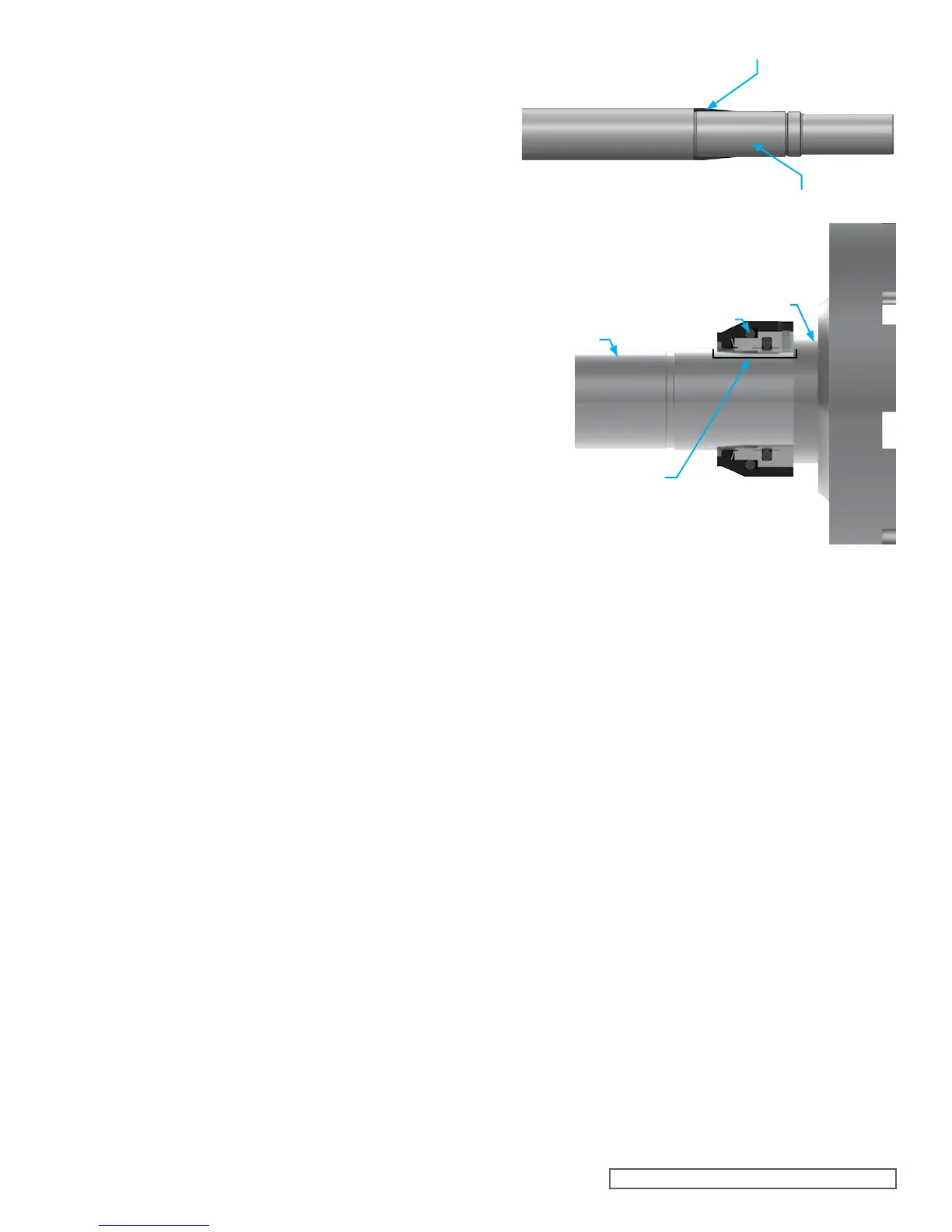
4. Place a tapered installation sleeve on the shaft, see
Figure 8. Coat the rotor shaft, tapered installation sleeve
and inner diameter of the mechanical seal rotary member
with a generous amount of Molykote 55 or compatible
O-ring lubricant.
5. Slide the rotary member, lapped contact surface facing
away from the rotor, over installation sleeve on shaft
until just contacting the back of the rotor. See Figure 9.
Remove the installation sleeve. Tighten the setscrews
evenly to 90 in-lbs.
6. Install the rotor and shaft into the casing, slowly pushing
until the ends of the rotor teeth are just below the face of
the casing. Take care not to damage the seal seat.
7. Place the O-ring on the head and install the head and
idler assembly on pump. The pump head and casing
were marked before disassembly to insure proper
reassembly. If not, be sure the idler pin, which is offset
in the pump head, is positioned up and equal distance
between port connections to allow for proper flow of
liquid through the pump.
8. Tighten the head capscrews evenly.
9. If the pump was equipped with a relief valve and was
removed during disassembly, install on the casing with
new O-rings or gaskets. The relief valve adjusting screw
cap must always point towards the suction port. Refer to
Figure 2, page 3. For relief valve repair or adjustments,
see “Pressure Relief Valve Instructions,” page 8.
10. Coat the inner diameter of the bearings, bearing spacer,
and bearing spacer collar with an anti-fretting agent.
11. KE, KKE, LQE, LSE: Install the bearing spacer collar
over the shaft into the bore. See Figure 6. The Q and QS
do not contain a bearing spacer collar.
12. Pumps use “Sealed for Life” bearings that have seals on
both sides. The bearings can be installed either side first
and do not need to be packed with grease.
13. Install the bearing into the bore. Tap the inner race with
a brass bar and lead hammer to position bearing.
14. Install the bearing spacer over the shaft and against the
single row ball bearing. See Figure 8.
15. Install the ball bearing into the bearing housing. Install
the bearing spacer collar in the end cap and turn the
end cap into the bearing housing until tight against the
bearing. Lock in place with two set screws in the flange
of the bearing housing. See Figure 7.
16. Start the bearing housing assembly into casing. Turn by
hand until tight. Put lockwasher and locknut on shaft.
Insert length of hardwood or brass through port opening
between rotor teeth to keep shaft from turning. Tighten
locknut to 100-130 ft.- lbs. (KE, KKE), or 120 - 150 ft. –
lbs. (LQE, LSE), or 150 - 170 ft. – lbs. (Q, QS). Bend one
tang of lockwasher into slot of locknut. If tang does not
line up with slot, tighten locknut until it does. Failure to
tighten locknut or engage lockwasher tang could result
in early bearing failure and cause damage to pump.
17. Remove length of hardwood or brass from port opening.
18. Adjust pump end clearance, refer to “Thrust Bearing
Adjustment”, page 8.
FIGURE 8
MECHANICAL SEAL
(ROTARY MEMBER)
SPRING
ROTOR HUB
SHAFT
FIGURE 9
TAPERED INSTALLATION SLEEVE
SHAFT
 Loading...