SECTION TSM 144.1 ISSUE B PAGE 8 OF 10
1. Loosen the two set screws in the outer face of the
bearing housing and turn this thrust bearing assembly
clockwise until it can no longer be turned by hand. Back
off counter-clockwise until the rotor shaft can be turned
by hand with a slight noticeable drag. If the shaft cannot
be rotated freely, turn the thrust bearing assembly
counterclockwise until the shaft can be turned easily.
2. For standard end clearance, back off the thrust bearing
assembly the required length measured on the outside
diameter of the bearing housing. See Table 1 below.
3. After the adjustment is made, tighten the two setscrews
in the face of the bearing housing assembly to secure
the position. Your pump is now set with standard end
clearances and locked.
When installing the carbon graphite bushings, extreme care
must be taken to prevent breaking. Carbon graphite is a brittle
material and is easily cracked. If cracked, the bushing will
quickly disintegrate. Using a lubricant and adding a chamfer
on the bushing and the mating part will help in installation.
The additional precautions listed below must be followed for
proper installation:
1. A press must be used for installation.
2. Be certain the bushing is started straight.
3. Do not stop pressing the operation until the bushing is in
the proper position, as starting and stopping may result
in a cracked bushing.
4. Check the bushing for cracks after installation.
DANGER !
Before starting pump, be sure all drive
equipment guards are in place.
Failure to properly mount guards may
result in serious injury or death.
THRUST BEARING ADJUSTMENT
See Figures 6 and 7, page 6.
PUMP
SIZE
DISTANCE IN INCHES
ON O.D. OF BEARING
HOUSING
STANDARD
END
CLEARANCE
KE, KKE 5/8” .005”
LQE, LSE 5/8” .005”
Q, QS 11/16” .010”
INSTALLATION OF CARBON
GRAPHITE BUSHINGS
PRESSURE RELIEF VALVE
INSTRUCTIONS
DISASSEMBLY
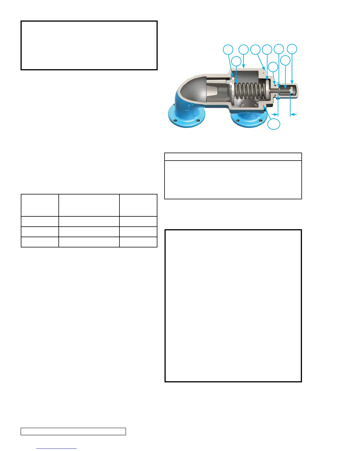
VALVE - LIST OF PARTS
V1. Valve Cap V6. Valve Body
V2. Adjusting Screw V7. Valve Spring
V3. Lock Nut V8. Poppet
V4. Spring Guide V9. Cap Gasket
V5. Bonnet V10. Bonnet Gasket
FIGURE 10
RELIEF VALVE - ALL SIZES
TABLE 1
V8
V7
V9
V10
V6 V5
V1V3
V4
V2
A
DANGER !
Before opening any Viking pump liquid chamber
(pumping chamber, reservoir, relief valve
adjusting cap fitting, etc.) Be sure:
1. That any pressure in the chamber has been
completely vented through the suction or
discharge lines or other appropriate openings
or connections.
2. That the driving means (motor, turbine,
engine, etc.) has been “locked out” or made
non-operational so that it cannot be started
while work is being done on pump.
3. That you know what liquid the pump has been
handling and the precautions necessary to
safely handle the liquid. Obtain a material
safety data sheet (MSDS) for the liquid to be
sure these precautions are understood.
Failure to follow above listed precautionary
measures may result in serious injury or death.
 Loading...