EasyManuals Logo

Viking DEVDSC305 Installation Guide

Viking DEVDSC305
20 pages
To Next Page IconTo Next Page
To Previous Page IconTo Previous Page
Page #10 background imageLoading...
Page #10 background image
9
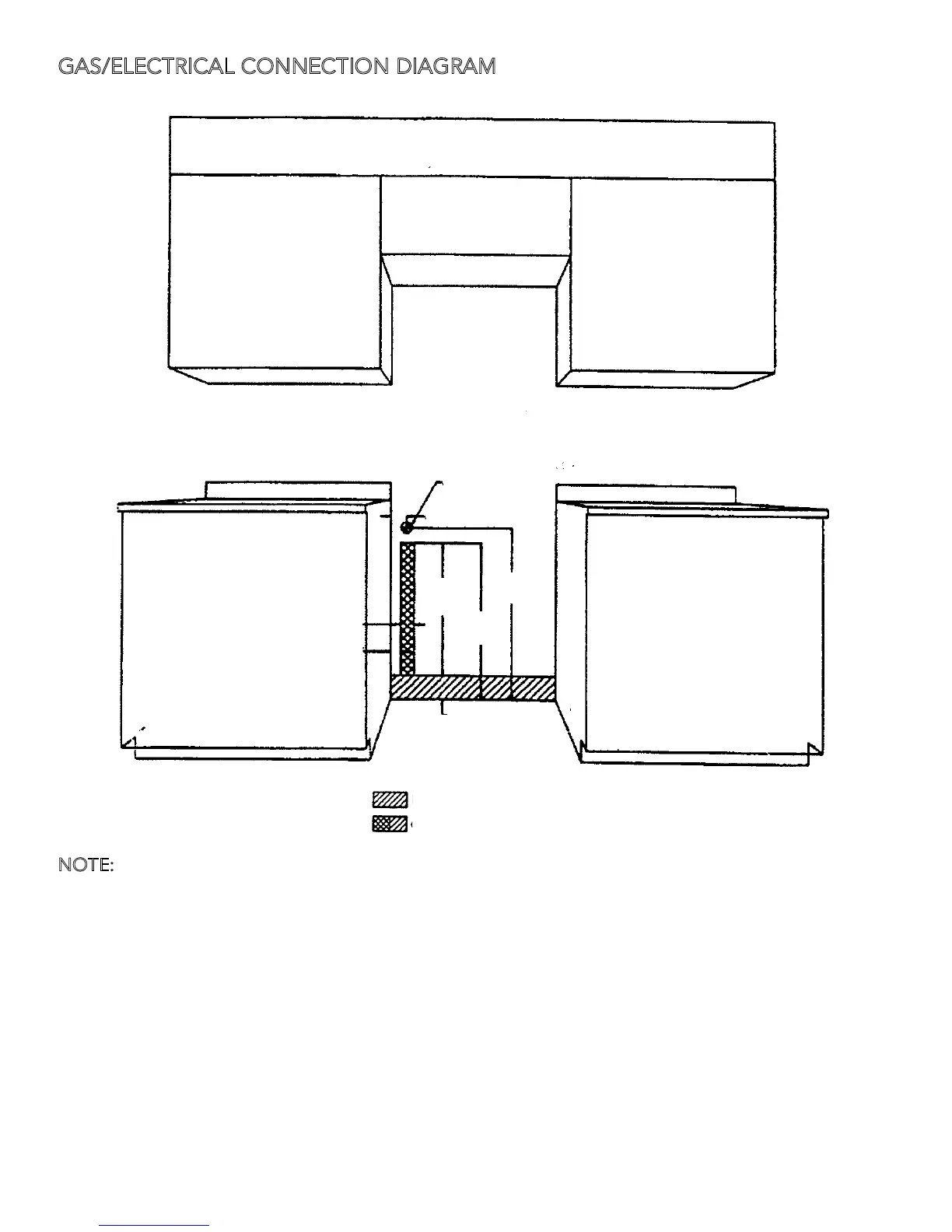
Electrical Connection in this area
Gas Connection in either area
2” (5.1 cm)
Dia.
2 3/4” (7.0 cm)
31 1/16”
(78.9 cm)
2 1/2”
(6.4 cm)
1 3/4”
(4.4 cm)
4 3/8”
(11.1 cm)
23 7/16”
(59.5 cm)
28 5/16”
(71.9 cm)
GAS/ELECTRICAL CONNECTION DIAGRAM
NOTE:
If the gas supply is installed through the rear wall, the location MUST be 31 1/16” (78.9 cm) above the floor
and 2 3/4” (7.0 cm) from the left hand side (when facing the unit) or within a maximum of 4 3/8” (11.1 cm)
above the floor as specified in the drawing above.

Other manuals for Viking DEVDSC305

Questions and Answers:

Question and Answer IconNeed help?

Do you have a question about the Viking DEVDSC305 and is the answer not in the manual?

Viking DEVDSC305 Specifications

General IconGeneral
BrandViking
ModelDEVDSC305
CategoryRanges
LanguageEnglish

Related product manuals