TECHNICAL SUPPORT 1 800 908 0884
15
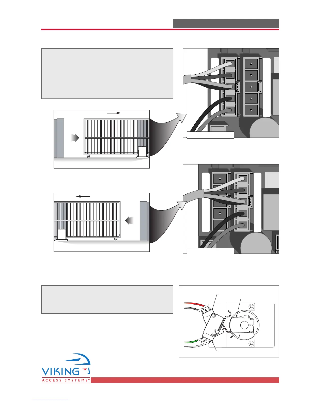
Power Connections
ELECTRICAL INSTALLATION ELECTRICAL INSTALLATION
Radio
Rec.
UL
Sensor
OPEN RIGHT
OPEN LEFT
Safety
Loop
Center
Loop
Obstruction
Sensor
Charger
Power
Low Battery
Motor Sensor
Obstruction
Sensor
min. MAX
Charger
Power
Low Battery
Motor Sensor
Radio
Rec.
UL
Sensor
Safety
Loop
Center
Loop
Radio
Rec.
UL
Sensor
OPEN RIGHT
OPEN LEFT
Safety
Loop
Center
Loop
Obstruction
Sensor
Charger
Power
Low Battery
Motor Sensor
Obstruction
Sensor
min. MAX
Charger
Power
Low Battery
Motor Sensor
Radio
Rec.
UL
Sensor
Safety
Loop
Center
Loop
Gate Opens Right
Gate Opens Left
STEP 5
Connect the wire harness to the “OPEN RIGHT”
connector if the gate opens to the right.
Connect the wire harness to the “OPEN LEFT”
connector if the gate opens to the left.
Inside View
Inside View
OPEN
OPEN
Limit Switch Connections
The Limit Switches are pre-wired. Should the
wires become disconnected, use this diagram
to reconnect them.
Lower Limit Switch
Red
Black
Green
White
Upper Cam
Upper Limit Switch
NC
NO
COM
NC
NO
COM
 Loading...