Do you have a question about the Viking G-5 and is the answer not in the manual?
Key safety guidelines to reduce the risk of severe injury or death.
Crucial guidelines for proper gate operator installation to ensure safety.
Essential precautions for safe use, installation, and maintenance of the product.
Defines the classification system for gate operators according to UL 325 standard.
Procedures for keeping the gate operator in good working condition.
General safety rules and manufacturer responsibilities for product use.
Mandatory safety sensor requirements for compliance with UL 325.
Step-by-step guide for installing monitored entrapment protection sensors.
Procedure for manually operating the gate in case of power failure or malfunction.
Instructions for installing and using the audible alarm reset switch.
Guidelines for proper placement of control buttons for user safety.
Instructions for installing warning placards for gate area safety.
Table detailing appropriate motor cable gauge based on length.
Diagram and dimensions for installing the gate operator in a pull-to-open configuration.
Diagram and dimensions for installing the gate operator in a push-to-open configuration.
Step-by-step guide for mounting the gate operator to brackets.
Instructions and options for mounting the gate operator on posts.
Procedure for setting the gate's open and close limit switches correctly.
Instructions for connecting the gate operator to a high voltage power source.
Instructions for powering the gate operator using a low voltage AC supply.
Guidance on connecting and configuring the gate operator for solar power.
Wiring instructions for connecting the primary motor in a single-gate system.
Wiring instructions for connecting the secondary motor in a dual-gate system.
How to connect monitored entrapment protection sensors to the control board.
Configuration of key operator parameters like speed, delay, and timers.
Adjusts the gate operator's travel speed.
Sets delay for dual gates to prevent opening/closing conflicts.
Configures sensitivity for obstruction detection to prevent entrapment.
Sets the automatic closing time for the gate.
Gate automatically opens during power failure.
Gate opens automatically when battery backup is critically low.
Determines manual gate movement force during power failure.
Activates audible/visual warning before gate motion.
Synchronizes operation with Barrier Arm Operators.
Detailed explanation of the Obstruction Detection Sensor (ODS) function and settings.
Enables and configures the integrated heater for cold weather operation.
Activates the lock mode feature for securing the gate at the closed position.
Wiring and terminal functions for connecting access control devices.
Glossary of terms and definitions for relay connections and terminals.
Instructions for wiring and programming the radio receiver for gate control.
Instructions for connecting a photocell for safety and entrapment prevention.
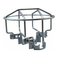
Information on connecting loop detectors using the Viking Loop Rack system.
Best practices for installing loop sensors for optimal vehicle detection.
Wiring instructions for magnetic locks and lock solenoids for enhanced security.
Procedure for synchronizing gate operator operation with barrier arms.
Explanation of Control Board LED indicators and their meanings for troubleshooting.
Explanation of LCD display messages and status codes for troubleshooting.
Troubleshooting steps and checks based on error messages and status indicators.
Technical specifications and ratings for the Viking Solar ECU.
Guidance on selecting and using appropriate batteries for the Solar ECU.
Recommendations for battery care, handling, and placement in the Solar ECU system.
Information on selecting and using UL listed solar panels for the system.
Guidelines for optimal placement, care, and environmental conditions for solar panels.
Safety warnings and precautions for installing solar panels and related equipment.
Methods and requirements for securely mounting solar panels according to codes.
Step-by-step instructions for connecting power sources to the Solar ECU.
Tip on how the Solar VFlex Control Board conserves power in sleep mode.
Explanation of Solar ECU LED indicators and their meanings for troubleshooting.
Explanation of Solar ECU LCD messages for troubleshooting.
Troubleshooting steps and checks based on error messages and status indicators.
Kit for secure primary/secondary communication between gate operators.
Tool for off-site access to operator diagnostics and firmware updates.
Adds protection to the high voltage power supply from surges.
Kit providing sufficient solar power for general applications.
| Category | Gate Opener |
|---|---|
| Motor Type | DC motor |
| Safety Features | Obstruction sensing, Overload protection |
| Remote Control | Yes |
| Model | Viking G-5 |