VIKING TECHNICAL SUPPORT 1.800.908.0884
14
GATE OPERATOR INSTALLATION
Mounting the Gate Operator
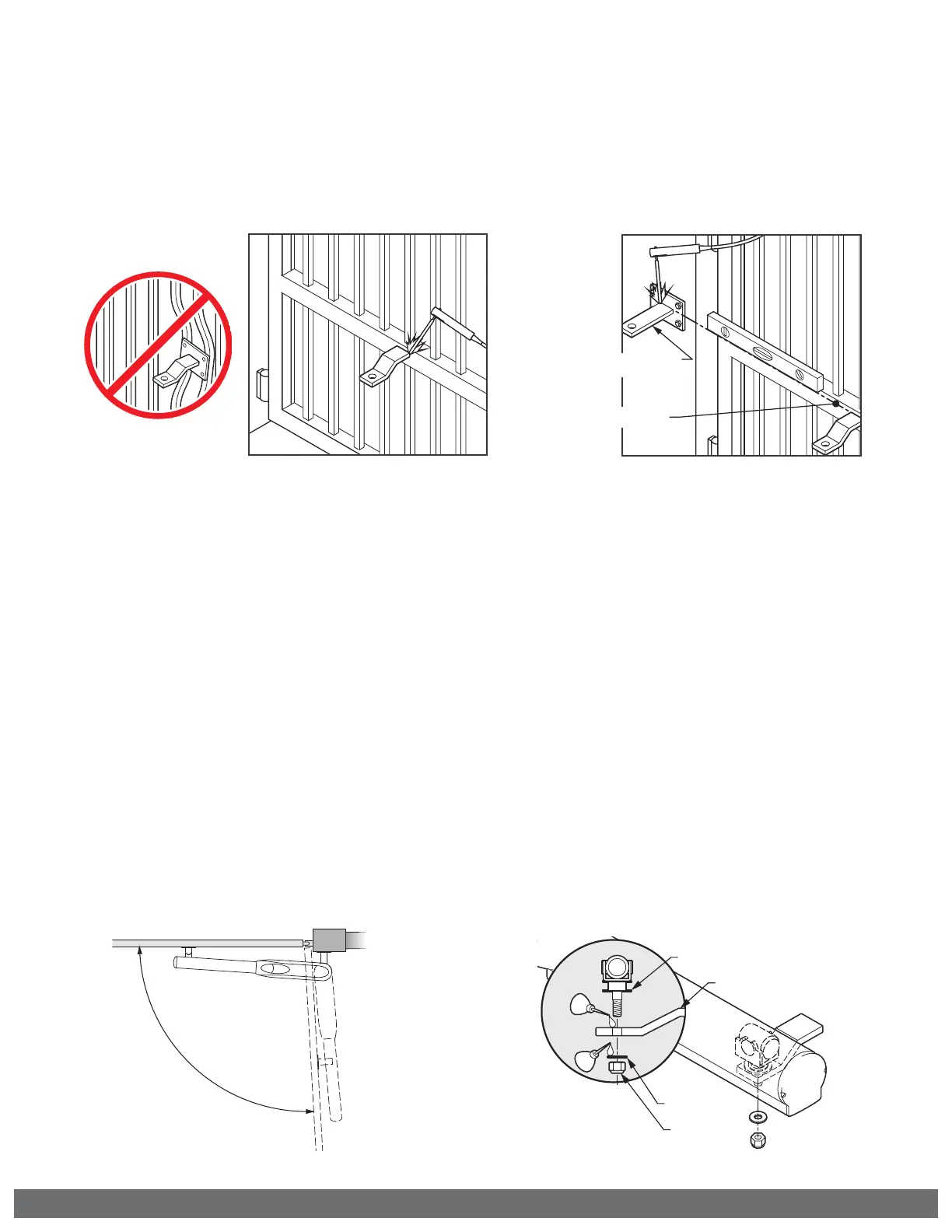
! Caution: If the Front Mounting Bracket is not attached to a frame member that
runs the full length of the gate, the gate operator may damage the gate. DO NOT
attach the bracket or backing plate to just a few pickets.
Refer to Dimensions
A & B for positioning
Level Line
Check Operation
Through Entire
Range of
Movment
Lead Screw Carrier
Front Mounting Bar
Small Flat
Washer
Lock
Washer
STEP 1
Front Mounting Bracket:
a.
Position the bracket according to the
dimensions provided on pages 12 or 13.
b.
Ensure the bracket is level and tack
weld in place.
! TIP: Alternatively, if you choose to bolt
this bracket to the gate, a backing plate
has been provided with four bolt holes.
STEP 2
Back Mounting Bracket:
a.
Cut and position the bracket according
to pages 12 or 13.
b.
Ensure the bracket is level and tack
weld in place.
! TIP: Alternatively, if you choose to bolt
this bracket to the gate, a backing plate
has been provided with four bolt holes.
STEP 3
Mount the Gate Operator:
a.
Install the operator onto the mounting
brackets using the hardware provided.
b.
Place the Manual Release Switch in the
“Release” position. Refer to page 7.
c.
Manually move the gate to ensure the
gate and operator move freely.
STEP 4
Complete the Installation:
a.
Dismount the operator.
b.
Complete the welding process.
c.
Lubricate the front bracket pivot point.
d.
Reinstall the gate operator and verify
once again that the gate moves freely.
e.
Place the Manual Release Switch back
to the “Engage” position.


 To Next Page