VIKING TECHNICAL SUPPORT 1.800.908.0884
20
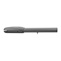
Motor Cable - Primary (Single)
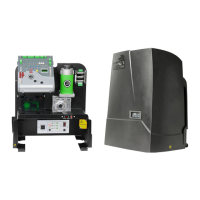
NOTE: The Single Electronic Control Unit is equipped to operate a single gate motor only,
and does not include a Secondary Module. The steps described on page 21 do not apply
for this type of application.
ELECTRICAL INSTALLATION - STANDARD ECU
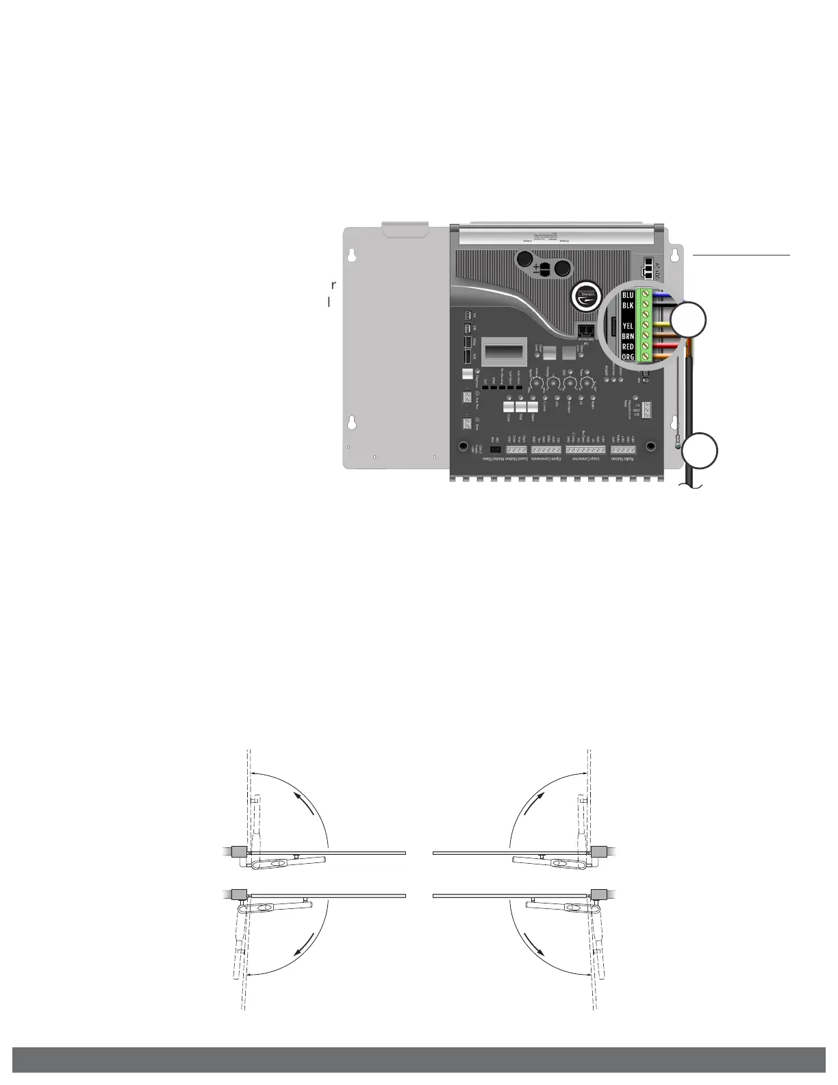
STEP 4
Primary Open Left or Open Right:
Place the terminal block in the proper location for the gate opening direction.
•
“OPEN RIGHT” Connector if the gate opens to the INSIDE (pull to open).
•
“OPEN LEFT” Connector if the gate opens to the OUTSIDE (push to open).
OPEN RIGHT
OPEN RIGHT
OPEN LEFT
OPEN LEFT
Inside
Outside
Open
Open
Open
Open
STEP 3
Primary Motor:
a.
Connect motor cable to the Motor
Connector at the Primary Control
Board as illustrated, according to
the printed color code.
b.
Attach the grounding wire, non
insulated, to the Board Mounting
Plate using the screw provided.
3b
3a
Primary Motor
BLUE
BLACK
NOT CONNECTED
YELLOW
BROWN
RED
ORANGE
 Loading...