Troubleshooting
14 ©2012 Viking Preferred Service
To avoid risk of electrical shock, personal injury, or death, disconnect electrical power source to unit, unless test
procedures require power to be connected. Discharge capacitor through a resistor before attempting to service.
Ensure all ground wires are connected before certifying unit as repaired and/or operational.
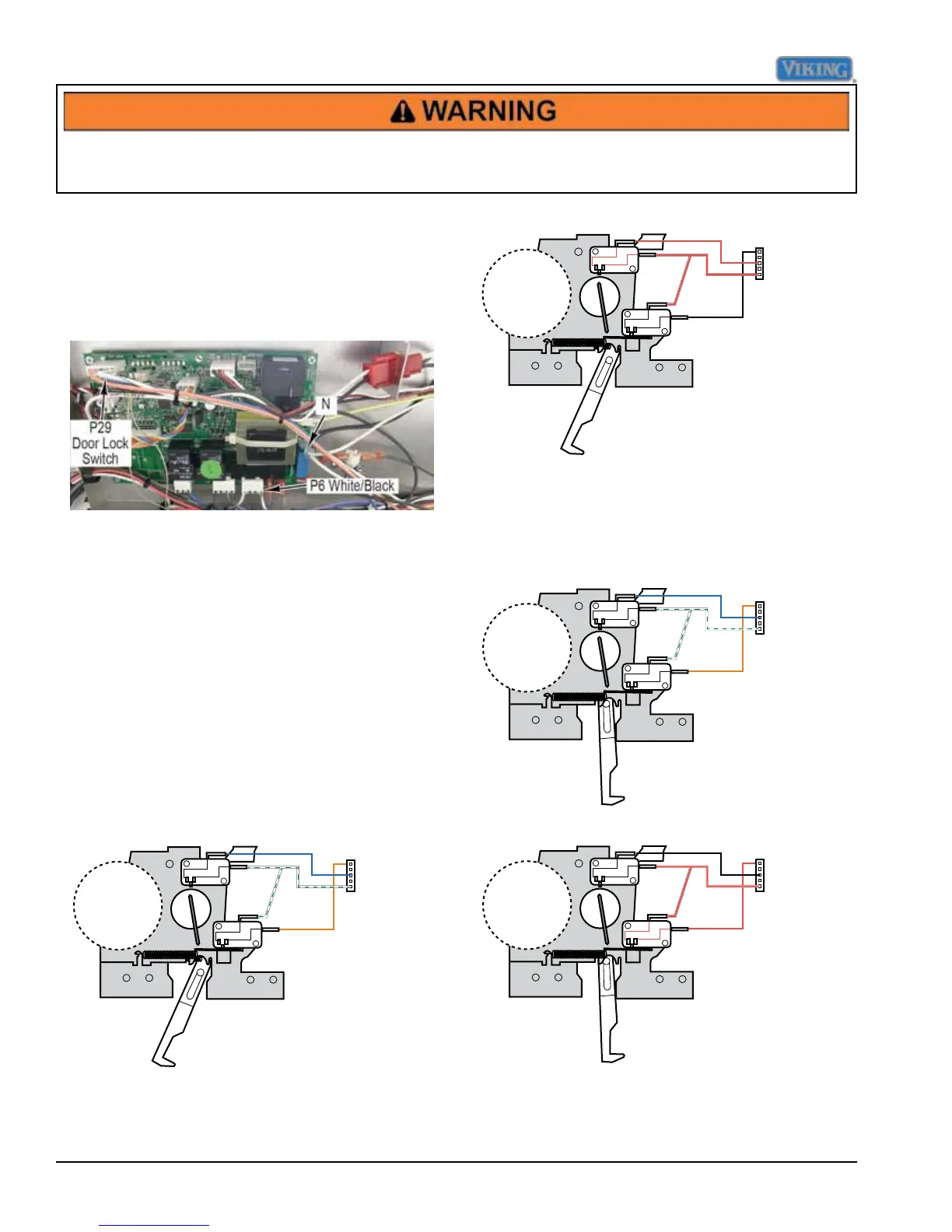
Testing Lock Motor
With the connector removed from the P6 board
connection, use an ohmeter to measure resistance
between neutral and the white/black wire at P6. The
resistance should be approximately 6.82K ohms. If no
resistance is read, remove the latch motor to repair/
replace (Follow the latch motor disassembly procedure).
Testing Latch Switches
To check the latch switches, access the control board
and unplug the P29 Molex plug. With the door in the
unlocked position, you should read continuity (0 ohms)
between the blue wire and the white/green wires, and
read infinite ohms (∞) between the white/green and
orange wires. If your readings are incorrect or reversed,
remove the latch and inspect, repair/replace (follow latch
motor disassembly procedure).
Checking the door lock position switches
With the door in the unlocked position, the S1 switch
(N.O.) is activated by the motor cam. Shown below
are the switch positions and wire colors. To test, check
continuity between the white/green and blue wires. The
reading should be 0 ohms. The S2 switch is N.O. and
will read infinite ohms (∞) when the door is unlocked.
Orange
Blue
White/Green
Motor
S1
S2 bottom
Note: (S3 - top switch not shown)
Shown below is the closed circuit in red.
Orange
Blue
White/Green
Motor
S1
S2 bottom
Note: (S3 - top switch not shown)
When the door locks, the S1 switch (N.O.) is no longer
in contact with the motor cam and will read infinite ohms
(∞). The S2 switch is N.O. and should close when the
door is locked. To test, check continuity between the
orange and white/green wires. The reading should be 0
ohms when the door is locked.
Motor
S1
Orange
Blue
White/Green
S2 bottom
Note: (S3 - top switch not shown)
Shown below is the closed circuit in red.
Motor
S1
Orange
Blue
White/Green
S2 bottom
Note: (S3 - top switch not shown)
 Loading...