Disassembly
©2012 Viking Preferred Service 25
To avoid risk of electrical shock, personal injury, or death, disconnect electrical power source to unit, unless test
procedures require power to be connected. Discharge capacitor through a resistor before attempting to service.
Ensure all ground wires are connected before certifying unit as repaired and/or operational.
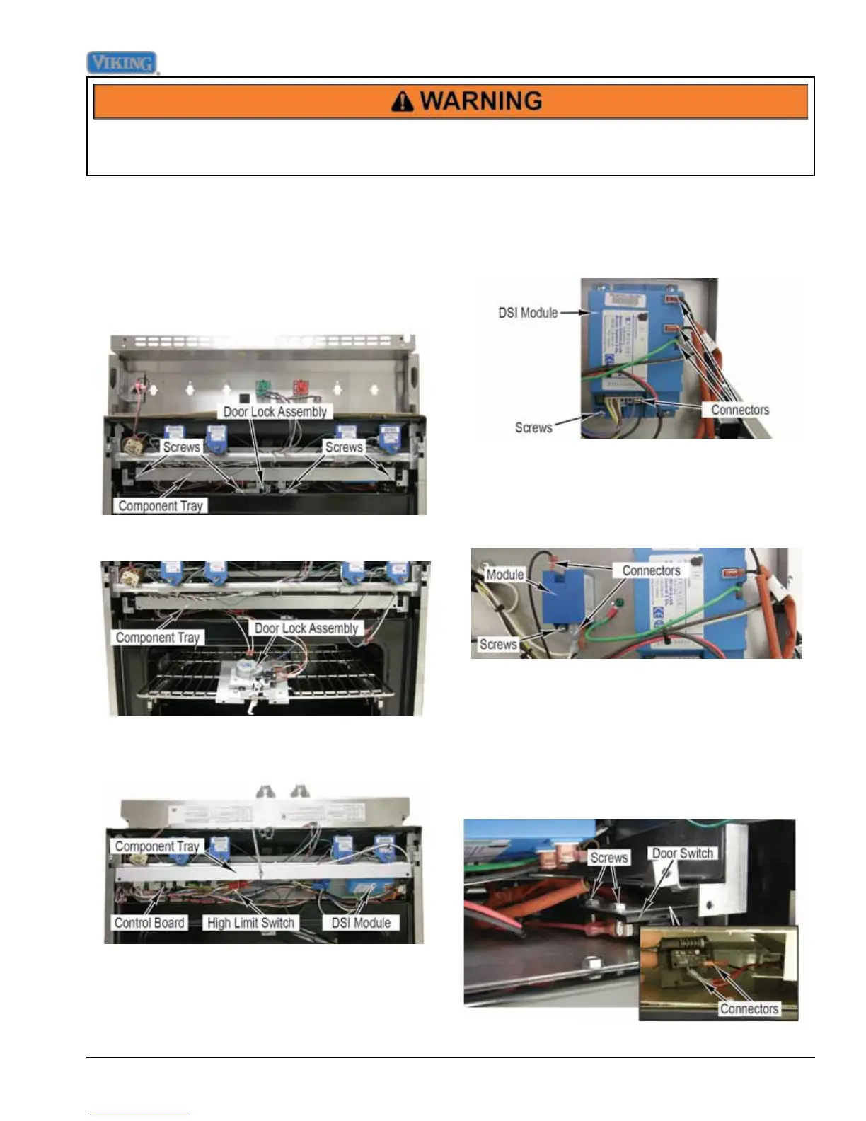
DSI Module and Control Board Accessed
The DSI Module and Control Board are located between
the rangetop and the oven cavity. Access is required in
order to perform many troubleshooting procedures.
1. Access control components (see Control
Components Accessed).
2. Remove screws from component tray and door lock
assembly.
3. Lift component tray and carefully remove door lock
assembly from range and place on top rack.
4. Carefully pull component tray forward and suspend in
horizontal position.
5. Reinstall door lock assembly.
Note: During installation, make sure all wires are
connected and are not pinched between the
component tray and burner box.
6. Reverse procedure for installation.
DSI Module Removal
1. Access DSI module (see DSI Module Accessed).
2. Mark and disconnect connectors from DSI module.
3. Remove screws and DSI module from component
tray.
4. Reverse procedure for installation.
Stack Valve Igniter Module Removal
1. Access DSI module (see DSI Module Accessed).
2. Disconnect connectors from module.
3. Remove screws and module from range.
4. Reverse procedure for installation.
Door Switch Removal
1. Access control components (see Control
Components Accessed).
2. Remove component tray screws (see DSI Module
and Control Board Accessed).
3. Remove screws and door switch from range.
4. Mark and disconnect connectors from door switch.
5. Reverse procedure for installation.
 Loading...