94
K40980 - K40981
EN
BUS+ BUS- COM
NO/NC
GND EXIT GND LOCK
+ - + -
IM OS
100 - 230V AC
D
E
C4
B
GND
BUS OUT
DC IN
BUS OUT
BUS IN
BUS IN
A1.1
GND
BUS OUT
DC IN
BUS OUT
BUS IN
BUS IN
A1.2
GND
BUS OUT
DC IN
BUS OUT
BUS IN
BUS IN
A1.3
GND
BUS OUT
DC IN
BUS OUT
BUS IN
BUS IN
A1.4
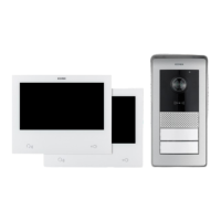
Wiring diagrams
(Connection of a four-family system with up to 4 indoor stations per apartment)
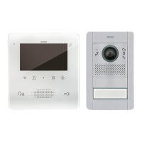
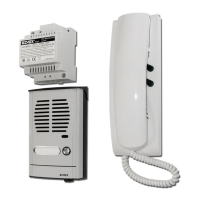
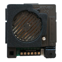
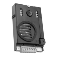
Outdoor station
2pushbuttons
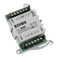
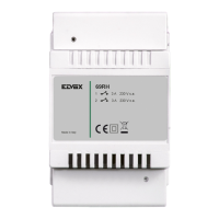
Powersupplyunit
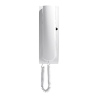
Apartment1
videoentryphone,
indoor1(master)
Apartment1
videoentryphone,
indoor 2
Additionallock
pushbutton
Electriclock
Apartment1
videoentryphone,
indoor 3
Apartment1
videoentryphone,
indoor 4
Toapartment2 Toapartment4Toapartment3
• Maximum distance from the power supply unit to the outdoor
station:
- 150 m (with two-wire cable, preferably twisted with section 1
or 1.5 mm
2
);
- 120 m (with UTP Cat. 5e or Cat. 6 cable with 4 twisted pairs).
• Maximum distance from the power supply unit to the farthest
video entryphone:
- 150 m (with two-wire cable, preferably twisted with section 1
or 1.5 mm
2
);
- 120 m (with UTP Cat. 5e or Cat. 6 cable with 4 twisted pairs).
• Two-wire cable, preferably twisted with section 1–1.5 mm2, or
Cat. 5e cable with 4 twisted pairs.
• Maximum length for connections to powered lock and relay:
30m; towards door release button: 10 m
N.B.: the devices can be connected to the power supply unit with
a star topology, a daisy-chain connection (i.e. in-out connection)
or a mixed connection (star and daisy-chain).