13
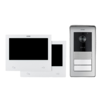
K40980 - K40981
EN
Video door entry system installation
General considerations:
The procedure to follow when installing a IPo2W video door entry system is described below.
1) Beforeactivatingthevideodoorentrysystem,takecaretondasuitablelocationforeachcomponent.
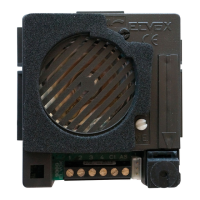
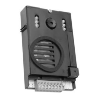
What’smore,makesureyoucongurethedipswitchesoftheoutdoorstationsrst(master/slavedevice;assignID,number
ofbuttonsanddefaultactuatortoactivatethelockfromtheexitpushbuttonorfromthelockreleasepushbutton),see
chapterentitled"OutdoorStationCongurationandConnection".
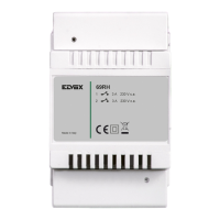
2) Makesureyouconnecttheoutdoorstationandeachindoorstationtothesystempowersupplyunit.
Connectioncablesthatcanbeused:
o Two-wirecablewithasectionof1or1.5mm
2
:maximumdistancebetweenthepowersupplyunitandfarthestdevice:150
m.
o UTPCat.5eorCat.6cablewith4twistedpairs:maximumdistancebetweenthepowersupplyunitandfarthestdevice:
120m.
3) Alwaysconnecteverydeviceinthesystembeforeactivatingthesystem,i.e.connectthepowersupplyunittothemains
power.
4) Checkthatthecomponentsareactivatedcorrectly:
a. ThesystempowersupplyunitisactiveiftheredstatusLEDison
b. Theoutdoorstationisactiveifcoveringthelightsensorturnsonthecallbuttonbacklighting
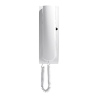
c. Theindoorstationsareactiveifthedisplayisactiveandreadyforcongurationattheendofthestart-upprocedure
(whichtakesapproximately20sandissignalledbytheashingmessagesicon).
d. TheIPo2WconvertersareactiveifthegreenLEDnexttotheEthernetcableconnectorison.
5) Connecttheadditionalwiring(locks,doorreleasebuttons,sensors,etc.)toeachdeviceasspeciedintherelevant
paragraphs.
6) Thevideodoorentrysystemcanbeusedoncetheindoorstationshavebeencongured.
Note:inanIPo2Wsystem,theindoorstationsmustbethelastdevicestobecongured.Infact,tooperatecorrectly,thesedevices
mustdetecttheoutdoorstationswithwhichtointeractwhiletheyarebeingcongured.
TheIPo2WsystemisdesignedtouseseveraltypesofBUSconnection:
- Star
- Daisychain(orin-out)
- Mixed(staranddaisychain)
Rememberthatthe2-wireBUSoftheIPo2Wsystemisnon-polarised,sothereisnoneedtoconnecttheterminalsattheindoor
station/outdoorstationendinaparticularorder.