95
K40980 - K40981
EN
C1.1
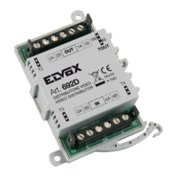
BUS+ BUS- COM
NO/NC
GND EXIT GND LOCK
+ - + -
IM OS
100 - 230V AC
D
E
B
BUS+ BUS- COM
NO/NC
GND EXIT GND LOCK
D
E
BUS+ BUS- COM
NO/NC
GND EXIT GND LOCK
D
E
BUS+ BUS- COM
NO/NC
GND EXIT GND LOCK
D
E
C1.2 C1.3 C1.4
Wiring diagrams
• Variant of a system connection with several outdoor stations (up to 4)
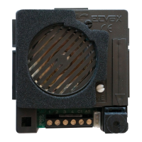
Outdoor station 1
(ID1)
Master
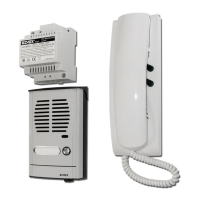
Powersupplyunit
Additionallock
pushbutton
Electric
lock
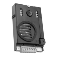
Outdoor station 2
(ID2)
Outdoor station 3
(ID3)
Electric
lock
Electric
lock
Electric
lock
Outdoor station 4
(ID4)
Additionallock
pushbutton
Additionallock
pushbutton
Additionallock
pushbutton
To the indoor
stations
• Maximum distance from the power supply unit to the outdoor station:
- 150 m (with two-wire cable, preferably twisted with section 1 or 1.5 mm
2
);
- 120 m (with UTP Cat. 5e or Cat. 6 cable with 4 twisted pairs).
• Maximum distance from the power supply unit to the farthest video entryphone:
- 150 m (with two-wire cable, preferably twisted with section 1 or 1.5 mm
2
);
- 120 m (with UTP Cat. 5e or Cat. 6 cable with 4 twisted pairs).
• Two-wire cable, preferably twisted with section 1–1.5 mm2, or Cat. 5e cable with 4 twisted pairs.
• Maximum length for connections to powered lock and relay: 30m; towards door release button: 10 m
N.B.: the devices can be connected to the power supply unit with a star topology, a daisy-chain connection (i.e. in-out connection)
or a mixed connection (star and daisy-chain).