5
SW24.W
EN
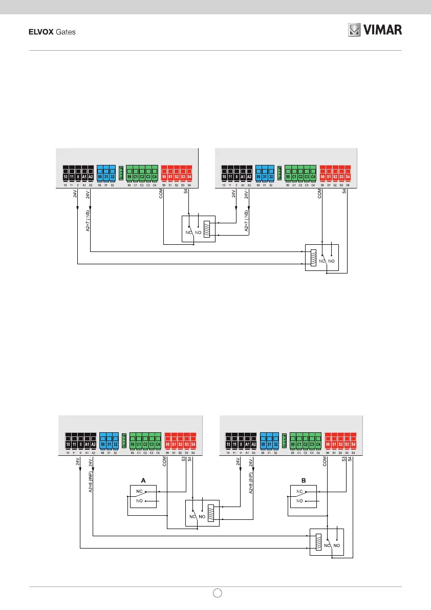
5.6 - Connecting two control panels in interlocking mode, output A2 = 7 (INB)
The interlocking connection involves 2 gates operating according to the following method:
- gate 1 opens only if gate 2 is closed
- gate 2 opens only if gate 1 is closed
When this mode is on, the safety input S4 is automatically congured without the installer selecting it as an interlock
input (checking that the other gate is closed).
The two control panels operating in interlocking mode must be connected by interposing 2 relays as shown in the gure:
5.7 - Connecting two control panels in interlocking mode with presence, output A2 = 8 (INP)
The interlocking connection with consent to opening from presence signal involves 2 gates operating according to the
following method:
- gate 1 opens only if gate 2 is closed
- gate 2 opens only if gate 1 is closed
- gate 1 opens only if there is a presence signal
- gate 2 opens only if there is a presence signal
When this mode is on, the safety input S4 is automatically congured without the installer selecting it as an interlock
input (checks the state of closure of the other gate) and the safety input S3 is congured automatically as the presence
input. The two control panels operating in interlocking mode must be connected by interposing 2 relays and using ac-
cessories which send the presence signals to the control panels (e.g. magnetic coils A and B) as shown in the gure:
AUX LSW ENC ACT SAF
AUX LSW ENC ACT SAF
AUX LSW ENC ACT SAF
AUX LSW ENC ACT SAF
AUX LSW ENC ACT SAF
AUX LSW ENC ACT SAF
AUX LSW ENC ACT SAF
AUX LSW ENC ACT SAF
 Loading...