21
SW24.W
EN
Signal Description
C1 Contact closed on command C1 input
C2 Contact closed on command C2 input
C3 Contact closed on command C3 input
C4 Contact closed on command C4 input
S1 Contact open on safety device S1 input
S2 Contact open on safety device S2 input
S3 Contact open on safety device S3 input
S4 Contact open on safety device S4 input
FO1 Opening limit switch position reached motor 1
FC1 Closing limit switch position reached motor 1
FO2 Opening limit switch position reached motor 2
FC2 Closing limit switch position reached motor 2
OB1 Obstacle detected motor 1
OB2 Obstacle detected motor 2
AF1 Motor in stop approach force reduction interval
AF2 Motor 2 in stop approach force reduction interval
MSO1 Mechanical stop reached in opening motor 1
MSC1 Mechanical stop reached in closing motor 1
MSO2 Mechanical stop reached in opening motor 2
MSC2 Mechanical stop reached in closing motor 2
BATT
“Operation with battery
When this message is displayed it is followed by an indication of the battery operating voltage, e.g.
24.5V"
BT- Battery almost at (indication shown only when the gate is stopped)
BT-- Battery totally at (indication shown only when the gate is stopped)
RX Radio command received from saved remote control or from App
NX Radio command received from unsaved remote control button
RD Rolling/xed code decoding o
OAB Gate left open
AT Gate in self-calibration
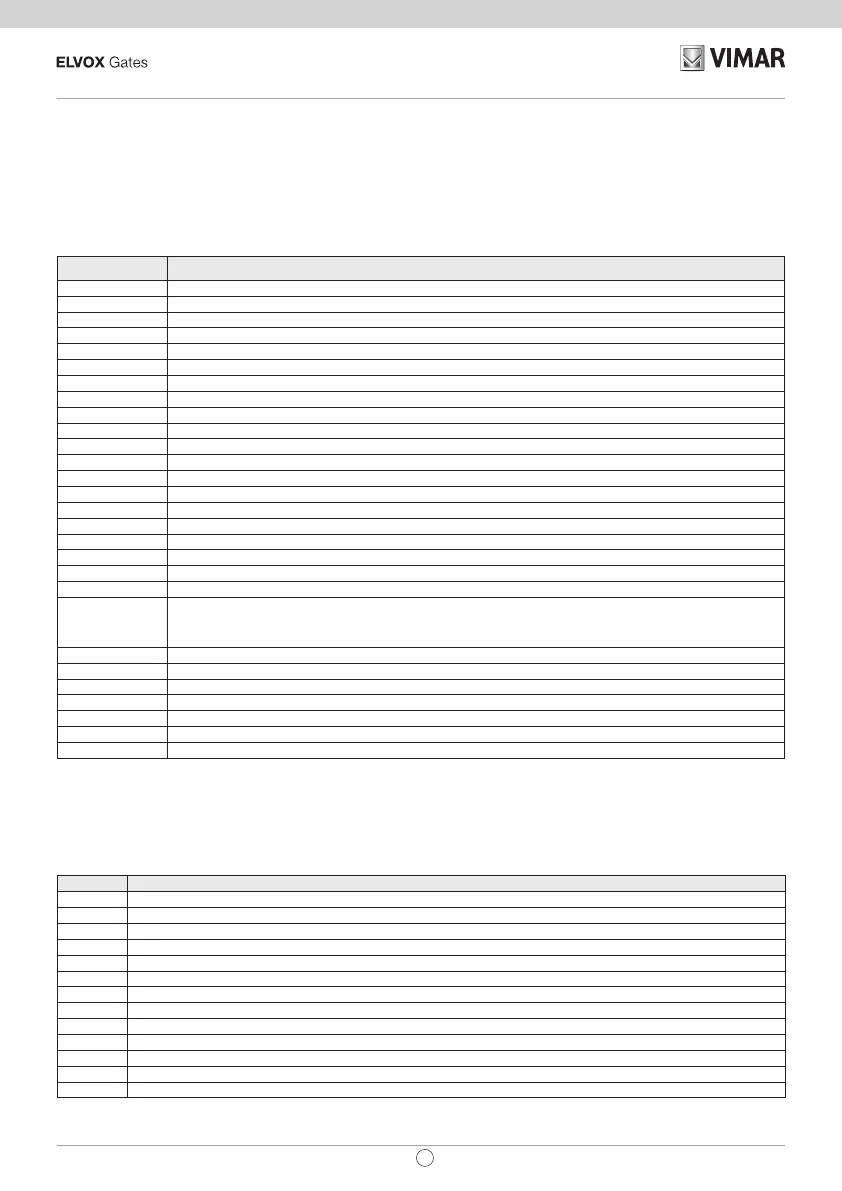
7 - Diagnostics:
7.1 - Signalling
Signalling indications are shown on the display for events of interest to the installer concerning normal and anoma-
lous operation. They appear on the display when the associated event occurs. These indications may signal a failure
if some of the system components are not working (e.g. photocells).
The following table gives the list of indications shown to the installer:
7.2 - Alarms
Alarms are generally indications on the display of operating failures which prevent the automation system from work-
ing. They appear on the display when the associated event occurs. The alarms generally signal wiring errors, but may
also indicate control panel or gear motor failures.
The following table gives the list of alarms shown to the installer:
Alarm Description
XXXX Reset card
MNP Manoeuvre interval since last maintenance reached alarm
F0 Error motor not selected
F1 Motor 1 cables inverted error
F2 Motor 2 cables inverted error
F3 Reversed limit switch error
F4 Both open limit switch alarm
F5 Opening limit switch malfunction error motor 1
F6 Closing limit switch malfunction error motor 1
F7 Opening limit switch malfunction error motor 2
F8 Closing limit switch malfunction error motor 2
F9 Communication error with expansion card
F10 Error alarm motor 1 not connected
 Loading...