Do you have a question about the Vimar TAB 7548 and is the answer not in the manual?
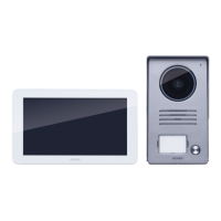
Detailed technical specifications of the video door entry system, including display, keypad, power, and environmental ratings.
Information on the device's compatibility and usage for individuals with hearing aids.
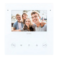
Guidance on the proper installation of the device, including recommended height and placement for optimal screen visibility.
Guidelines for qualified personnel regarding electrical installation compliance with local regulations.
Details on compliance with EMC directive and proper disposal of electronic waste.
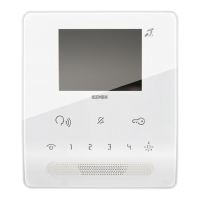
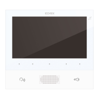
Enables automatic activation of cameras or cyclical viewing of the entrance panel cameras.
Mutes the chime or signals that the chime is muted, also indicates missed calls.
Unlocks the door or signals that the door is open.
Auxiliary function, typically for stair lighting.
Adjusts chime volume, contrast, and audio settings.
Adjusts the screen brightness.
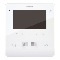
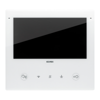
Enables self-start and cyclical camera viewing from the entrance panel.
Mutes chimes, signals muted chime, and displays missed calls.
Unlocks doors or indicates an open door status.
Controls the stair light or other auxiliary functions.
Adjusts chime volume, contrast, and voice unit settings.
Controls the screen brightness level.
Indicates incoming calls, including missed and configured calls.
Indicates if a door or window has been left open.
Signals that the device is in configuration mode.
Indicates potential alerts or warnings.
Notes that backlit buttons illuminate when touched, except for those under the handset.
Select DIP switch for BUS cable terminating in the internal station.
Configures termination for 100 Ohm BUS cable (Elvox 7321/732H) in terminal configuration.
Configures termination for 50 Ohm BUS cable (Cat.5/Cat.6) in terminal configuration.
Identifies terminals 1 and 2 for the digital BUS line connection.
Input for the local landing call button, referring to terminal M.
Specifies the maximum connection distance for the BUS line as 10 meters.
Input for the Alert function, configurable via SaveProg software.
Designates terminal M as the earth reference.
Diagram for connecting the indoor station in an in/out configuration.
Diagram for connecting the indoor station in a terminal configuration.
Wiring for video termination based on cable impedance.
Variant for connecting the landing or alert button.
Procedure for programming the unique identification code for the device.
Procedure for programming secondary IDs for multiple indoor units.
How to program buttons for intercom calls between units.
Procedure to program a button for specific electronic unit self-start.
Steps to reset the device programming to factory defaults.
How to select and save one of 10 different chime tunes for panel calls.
Guide to setting the chime volume to 10 different levels.
Instructions for temporarily muting the chime and its reactivation.
Adjusting brightness and volume levels during calls.
Important note on ID code configuration for device operation.
Procedure for answering incoming calls from outdoor panels or intercoms.
Details on landing calls using the FP/M connection variant.
How to make calls to other indoor units using programmed buttons.
Explanation of the LED behavior indicating missed calls.
How to send the unlocking command using the button.
Procedure for self-starting the master panel using a dedicated button.
How to call the concierge switchboard if it is installed.
System setup for sending alerts to the switchboard operator.
Using SaveProg to configure alert characteristics like enabling and delay.
Introduction to SaveProg software for advanced device configuration.
Instructions for updating the device firmware via USB connection.
Corresponds to the primary identification number for a group of devices.
Corresponds to secondary identification numbers for devices within a group.
First secondary ID mapping for a master group.
Second secondary ID mapping for a master group.
Third secondary ID mapping for a master group.
| Type | Video Intercom |
|---|---|
| Display | 7-inch TFT LCD |
| Mounting | Wall-mounted |
| Wiring | 2-wire |
| Resolution | 800 x 480 pixels |
| Touchscreen | Yes |
| Camera | Yes |
| Night Vision | Yes |
| Operating Temperature | -10°C to +55°C |
| Weight | 450 g |
| Housing Material | Plastic |
| Power Consumption | 10W |
| Compatibility | Vimar systems |