Do you have a question about the Viper 300+ and is the answer not in the manual?
Secure placement for optimal transmitter range and accessibility.
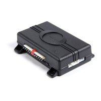
Locating and connecting the constant 12V power source.
Identifying the vehicle's ignition wire for system operation.
Locating the positive (+) parking light wire for system functions.
Identifying the door trigger wire for alarm activation.
Locating and interrupting the vehicle's starter wire.
Interfacing with positive pulse factory door lock systems.
Interfacing with negative pulse factory door lock systems.
Connecting to reversing polarity door lock systems.
Controlling aftermarket door lock actuators.
Starter disable function for anti-theft.
Entering and exiting the system's Valet Mode.
Diagnosing issues with the starter kill function.
Diagnosing problems with the shock sensor.
| Category | Car Alarm |
|---|---|
| Remote Start | No |
| Keyless Entry | Yes |
| Shock Sensor | Yes |
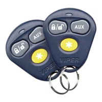
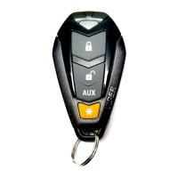
| Number of Buttons on Remotes | 4 |
| Number of Remotes Included | 2 |
| Remote Control | Yes |
| Starter Kill | Yes |
| Door Lock Control | Yes |
| Trunk Release | Yes |
| Panic Mode | Yes |
| Valet Mode | Yes |
| Remote Start Ready | No |
| Battery Backup | No |
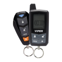
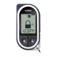
| System Type | 2-Way |
| Alarm Type | 2-Way Security System |
| Model | Viper 300+ |