EasyManua.ls Logo

Viper 330V User Manual

Viper 330V
43 pages
To Next Page IconTo Next Page
Page #1 background imageLoading...
Page #1 background image
© 2005 Directed Electronics, Inc. Vista, CA N427V 05-05
MMooddeell 333300VV
IInnssttaallllaattiioonn GGuuiiddee
Question and Answer IconNeed help?

Do you have a question about the Viper 330V and is the answer not in the manual?

Viper 330V Specifications

General IconGeneral
BrandViper
Model330V
CategoryCar Alarm
LanguageEnglish

Summary

Product Contents and Preparation

Installation Preparation Steps

Crucial advice and tools needed for installation.

Component Placement Guidance

Control Module Location Strategy

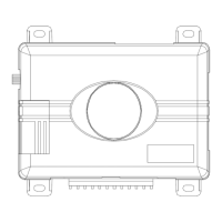
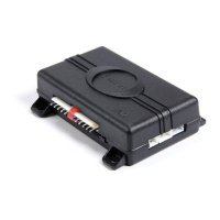
Advice on choosing a secure and accessible location for the control module.

Key Component Installation

Starter Kill Relay Security

Best practices for installing the starter kill relay securely.

Basic Wiring Connections

Finding Constant 12V Power

Procedure for locating and connecting the constant 12V power source.

Identifying Switched Ignition Wire

Steps to find the 12V switched ignition wire.

Vehicle Wire Identification

Locating the Parking Light Wire

Method for identifying the parking light wire using a multimeter.

Door Trigger Circuit Identification

Finding the Door Pin Switch Circuit

Procedures to locate the door trigger wire.

Main Harness Wiring Guide

Main Harness Wiring Diagram

Visual representation of main harness connections.

H1/5 Green: Negative Door Trigger Input

Explains the negative door trigger input.

H1/6 Blue: Instant Trigger Input

Describes the instant trigger input.

H1/7 Violet: Positive Door Trigger Input

Details the positive door trigger input.

H1/8 Black: Chassis Ground Connection

Explains the chassis ground connection.

H1/9 Yellow: Ignition Input Connection

Details the ignition input wire.

H1/11 Red: Constant Power Input

Details the constant 12V power input.

Auxiliary Harness Wiring Guide

Auxiliary Harness Wiring Diagram

Visual guide for auxiliary harness connections.

H2/2 Green: Arm Input

Details the arm input wire.

H2/3 Red: Disarm Defeat Input

Describes the disarm defeat input.

System Interface Ports

Door Lock Learn Routine Steps

Learn Lock Polarity Procedure

Step-by-step guide to learn lock polarity.

Learn Unlock Polarity Procedure

Step-by-step guide to learn unlock polarity.

Configuration Settings

Feature Programming Procedures

Entering Feature Programming Mode

Steps to access the feature programming routine.

Bitwriter® Exclusive Features

Features Menu #1 Overview

Features Menu #2 Overview

Detailed Feature Descriptions (Bitwriter®)

Menu #1 Feature Details

Menu #2 Feature Details

Troubleshooting Common Issues

Starter Kill System Malfunctions

Troubleshooting steps for the starter kill relay.

Valet Switch and LED Issues

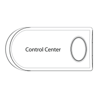
Resolving problems with the valet switch and status LED.

Troubleshooting Routine Failures

Door Lock Learn Routine Errors

Troubleshooting failures in the door lock learning process.

Feature Programming Entry Failures

Troubleshooting issues entering feature programming.

Wiring Quick Reference Guide

Related product manuals