10
© 2005 directed electronics, inc.
2. In most cars, fasten the (+) probe of your meter to (+)12V constant.
3. Probe the wire you suspect of being the door trigger wire. If the meter reads
(+)12V when any door is opened and the meter goes to 0 with the door closed,
you have found a trigger wire.
NNOOTTEE
: Make sure the wire you use “sees” all the doors! Some newer vehicles lack
standard-type pinswitches. The dome light in these vehicles is turned on when the door
handle is lifted. These usually have a wire coming out of the door into the kick panel
which will provide a (-) trigger for all doors.
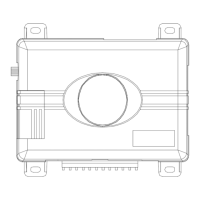
main harness wire connection guide
main harness wiring diagram
___
___
___
___
___
___
___
___
___
___
___
___
RED/WHITE (-) 200mA Auxiliary Channel/Delayed Accessory Output
RED (+) 12V Constant Power Input
BROWN (+) Siren Output
YELLOW (+) Ignition Input
BLACK (-) Chassis Ground Input
VIOLET (+) Door Trigger Input
BLUE (-) Instant Trigger (Hood and Trunk Pin)
GREEN (-) Door Trigger Input
BLACK/WHITE (-) 200mA Domelight Supervision Output
WHITE/BLUE No Function
WHITE (+)/(-) Light Flash Output
ORANGE (-) 500mA Ground When Armed
H1/1
H1/2
H1/3
H1/4
H1/5
H1/6
H1/7
H1/8
H1/9
H1/10
H1/11
H1/12