© 2012 Directed. All rights Reserved. 1
Quick Reference Install Guide
Vehicle Security System
Models 3105 and 3305
Guide Translations
For a Spanish or French version of the Installation Guide, please download it
from www.directechs.com under “Resources”.
Traducción de los manuales:
Para obtener una versión en Español o Francés del Manual de Instalación,
descárguela de www.directechs.com bajo el título “Recursos” (“Resources”).
Traduction du guide:
Pour une version française ou espagnole du guide d’installation, veuillez le
télécharger à www.directechs.com sous «Resources».
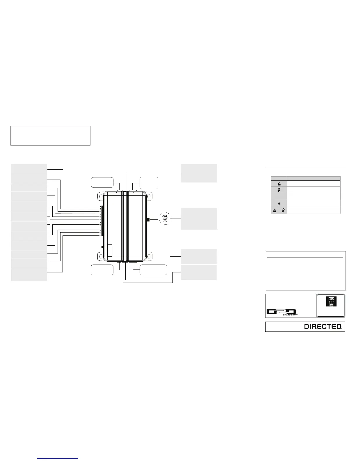
Sensor adjustment
detail
Optional Sensor Port
White 4 Pin Plug
LED Port
White 2 Pin Plug
Vatet Switch Port
Blue 2 Pin Plug
Antenna
Port
(-)
(+)
Red/White (-) 200mA Chan 2 Output
Green (-) Lock, (+) Unlock Output
Blue (-) Unlock, (+) Lock Output
Light Flash Jumper
Red (+) 12V Constant Power
Brown (+) Siren Output
Yellow (+) Ignition Input
Black (-) Chassis Ground
Violet (+) Door Trigger Input
Blue (-) Instant Trigger Input
Green (-) Door Trigger Input
Black/White (-) Domelight Sprvsn Output
White/Blue (-) 200mA Chan 3 Output
White (+/-) Light Flash Output
Orange (-) 500mA GWA Output
Wiring Connections
Channel 2 Output: Connect to the
vehicle negative (-) trunk release re-
lay or other low current device
12V Constant Power: Remove the
inline fuse before connecting to a
wire that has (+) 12V at all times
Siren Output: Connect to the (+)
wire on the siren
Ignition Input: Connect to a wire
that has (+) 12V while the key is in
the run and crank positions
Chassis Ground: Connect to a
scraped (bare) metal surface in the
driver kick
Door Trigger Input: Connect to a
wrie that goes to (+) 12V when any
door is opened
Instant Trigger Input: Connect to a
wire that goes to ground (-) when
the hood or trunk are opened
Door Trigger Input: Connect to a
wire that goes to (-) ground when
any door is opened
Domelight Supervision Output:
Connect to a (-) wire that will turn on
the domelight
Channel 3 Output: Connect to an
auxiliary relay or low current device
Light Flash Output: Connect to the
vehicle parking light wire. This wire
is programmable + or -
Ground When Armed Output:
Connect to a starter interrupt relay
or other accessory that requires a
GWA
Important: NEVER connect 200mA low current outputs
directly to a motor or high current device WITHOUT a
relay,
Programming Port: The 998T Bit-
writer can be connected to this port
for programming feature options.
SmartStart can be connected to this
port to operate the system by Smart-
phone.
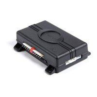
Adjusting the shock sensor pot:
1. Securely mount the CPU (in a
safe location) before adjusting
2. Turn the sensor adjustment
clockwise to increase sensitiv-
ity, turn counterclockwise to
decrease sensitivity
(-) Lock, (+) Unlock Output: Con-
nect to a wire that pulses ground to
activate the vehicle lock relay or to
a wire that pulses (+) 12V to acti-
vate the vehicle unlock relay
(-) Unlock, (+) Lock Output: Con-
nect to a wire that pulses (-) ground
to activate the vehicle unlock relay
or to a wire that pulses (+) 12V to
activate the vehicle lock relay
Bitwriters with a date code of 6a or older require an IC
upgrade (p/n 998M). Some bitwriters with a date code
of 6B do not require the IC upgrade, refer to tech tip #
1112 for more information.
The Bitwriter® (p/n 998U)
requires chip version 2.4 or
newer to program this unit.
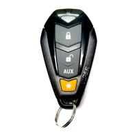
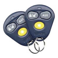
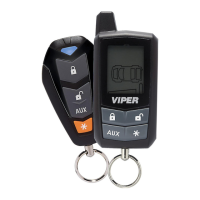
Remote control configuration
4- button remote control configuration
Feature Description
Arm: Lock the doors and arm the vehicle
Disarm: Unlock the doors and disarm the vehicle
AUX
Channel 2/Silent Mode: Activate Silent Mode and
Auxiliary functions
Panic
and
Channel 3: Press together to control an Auxiliary out-
put
More information and full Installa-
tion Guide can be found online at:
www.directechs.com