6
© 2015 Directed. All rights reserved.
Wiring Connections
Main Harness, White 6-pin connector
1
RED (+)12V DC CONSTANT INPUT
2 BLACK (-) CHASSIS GROUND
3 BROWN (-) 200mA HORN HONK OUTPUT
4 WHITE/BROWN PARKING LIGHT ISOLATION WIRE - #87a NORMALLY CLOSED of onboard relay
5 WHITE PARKING LIGHT OUTPUT- #30 COMMON of onboard relay
6 ORANGE (-) 500 mA (GWA) GROUND WHEN ARMED OUTPUT
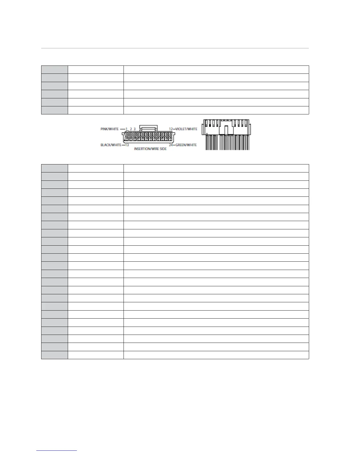
Auxiliary/Shutdown Harness, White 24-pin connector
1 PINK/WHITE (-) 200mA IGNITION 2/FLEX RELAY OUTPUT
2 BLUE/WHITE (-) 200mA 2ND STATUS/REAR DEFOGGER OUTPUT
3 RED/WHITE (-) 200mA TRUNK RELEASE OUTPUT
4 BLACK/YELLOW (-) 200mA DOME LIGHT OUTPUT
5 DARK BLUE (-) 200mA STATUS OUTPUT
6 WHITE/BLACK (-) 200mA AUX 3 OUTPUT
7 WHITE/VIOLET (-) 200mA AUX 1 OUTPUT
8 ORANGE/BLACK (-) 200mA AUX 4 OUTPUT
9 GRAY (-) HOOD PIN INPUT (N/O or N/C)
10 BLUE* (+) or (-) FACTORY HORN INPUT (Use Jumper to set polarity)
11 WHITE/BLUE ACTIVATION INPUT
12 VIOLET/WHITE** TACHOMETER INPUT
13 BLACK/WHITE*** (-) PARKING BRAKE/E-BRAKE INPUT
14 GREEN/BLACK (-) 200mA FACTORY ALARM DISARM OUTPUT
15 GREEN** (-) DOOR INPUT (N/O or N/C)
16 EMPTY ------------------------------------
17 PINK (-) 200mA IGNITION 1 OUTPUT
18 VIOLET** (+) DOOR INPUT
19 VIOLET/BLACK (-) 200mA AUX 2 OUTPUT
20 BROWN (+) BRAKE SHUTDOWN INPUT
21 VIOLET/YELLOW (-) 200mA STARTER OUTPUT
22 GRAY/BLACK (-) DIESEL WAIT TO START INPUT
23 ORANGE (-) 200mA ACCESSORY OUTPUT
24 GREEN/WHITE (-) 200mA FACTORY ALARM ARM OUTPUT
* This optional input can be connected to the horn circuit (+ or -) in vehicles with factory alarm. When this
wire receives input for a minimum of 5 seconds, the system reports a trigger on the 2-way remote.
** Required connection for manual transmission vehicles.
***Connect this wire to the (-) Parking Brake wire in the vehicle (see Owners Guide for manual transmission
procedure).
Important: NEVER connect 200mA low current outputs directly to a motor or high current device WITHOUT
a relay.