Assembly
www.visioneng.com/support
7
u
v
v w
w
w
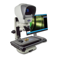
Stage alignment (video systems only)
` Turn on the system.
` Switch on the PC and follow on screen instructions for crossing reference marks.
` Using the Focus control
u
, focus on the three horizontal lines in the
centre of the alignment plate attached to the stage.
` Rotate the stage by hand until the horizontal lines are
parallel to the horizontal crosshair on the PC’s screen.
` Use the X axis control
v
to check reference lines remain
parallel with the crosshair.
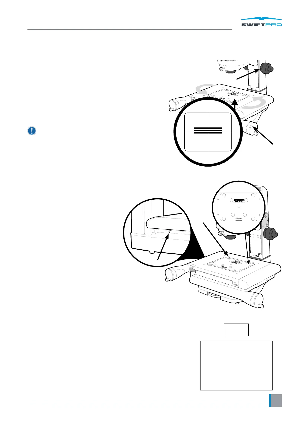
Before the alignment plate can be removed the
relevant stage securing procedure should be carried
out.
Securing the stage (150mm x 100mm & 200mm x 100mm)
With the stage assembled (see page 5) and aligned (see above),
secure the stage as follows:
` Being careful not to move the stage,
loosen the oating stage foot
securing screw
u
.
` Insert and screw in the last stage
bolt
v
and tighten until nger tight.
` Use the Allen key supplied to progressively
tighten all four screws through the
appropriate holes
v
and
w
in the alignment
plate in the numbered sequence (shown in the
diagram
x
below) to a torque of 2.8Nm.
(this is approximately equivalent to bolt touch
down plus 1/8th turn).
` Lightly tighten the oating stage foot securing screw.
u
v
Column
Stage Assembly
B4
B3B1
B2
x