Chapter 1
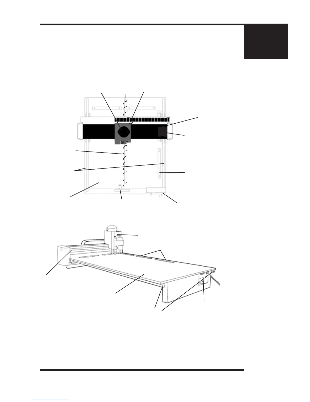
(Figure 1.3) Moveable gantry atbed table format.
Shown here is a top view of the Vision 2424.
1. Table Base Plate
2. X-Axis
Linear Rails
4. Gantry Assembly
5. Carriage Assembly
6. 25 Pin
Breakout Box
7. Y-Axis
Stepper Motor
8. X-Axis
Stepper Motor
9. Material Guides
10. Engraving Motor
3. X-Axis
Lead Screw
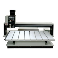
6. 25 Pin
Breakout Box
1. Table Base Plate
2. X-Axis Linear Rails
9. Material Guides
5. Carriage Assembly
4. Gantry Assembly
1. Table Base Plate. This is the large at plate upon which everything else is mounted. All
mechanical alignments are referenced to this plate, so the space upon which you place the
engraving table must be a reasonably level surface.
(Always carry the table by the base plate only.) An optional t-slot table may be installed on the
table base plate. Router tables include a t-slot table as standard.
2. X-Axis Linear Rails. Mounted under the table base plate are steel rails with sealed
bearings, which allow the motion of the gantry in the X-axis direction.
(Figure 1.3a) Front angled view of the Vision 2448