EasyManuals Logo

Vision 1612 User Manual

Vision 1612
40 pages
To Next Page IconTo Next Page
To Previous Page IconTo Previous Page
Page #16 background imageLoading...
Page #16 background image
Page 16
Chapter 3
4. Loosen all 4 Screws until you feel the
Spindle Block Plate has detached from the
Router Rail Plate.
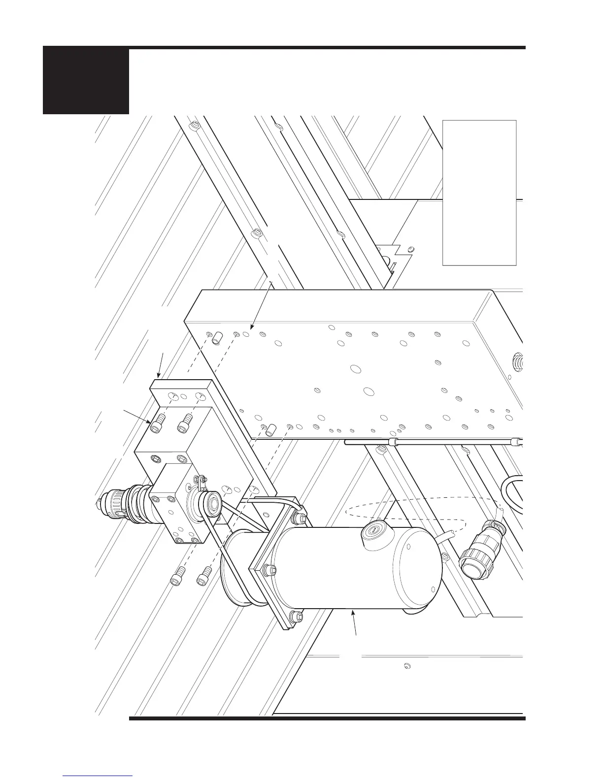
5. Then remove all 4 Screws (2 on the Right
and 2 on the Left) and detach the Engraving
Head Assembly from the Router Rail Plate.
Remove these 2 Screws on the
Left (then 2 on the Right Side)
Engraving Head
Assembly
Spindle Block
Plate
Router Rail Plate
Chapter 3: Engraving Head Removal Procedure (Part 2 of 2)

Table of Contents

Questions and Answers:

Question and Answer IconNeed help?

Do you have a question about the Vision 1612 and is the answer not in the manual?

Vision 1612 Specifications

General IconGeneral
BrandVision
Model1612
CategoryEngraver
LanguageEnglish

Related product manuals