Advent Communications
209297 – DCU5000 Drive Control Unit Page 36 of 42
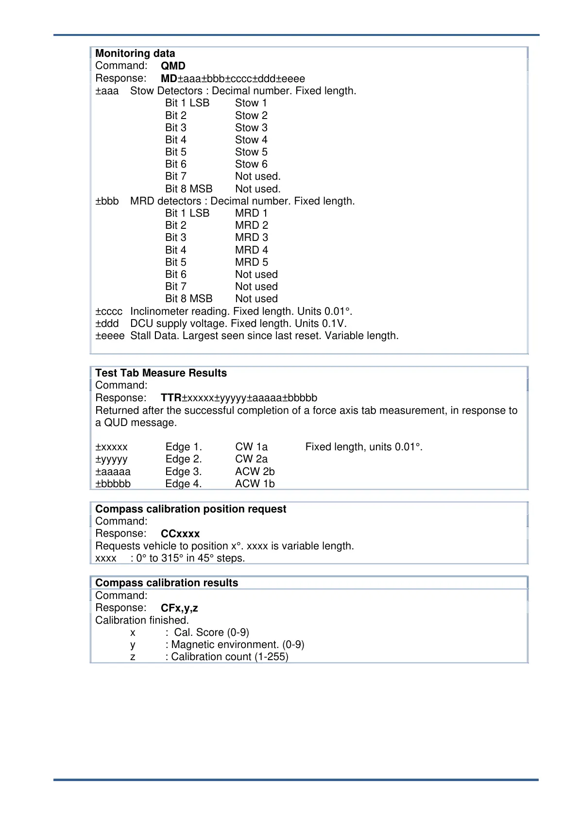
Monitoring data
Command:
QMD
Response:
MD±aaa±bbb±cccc±ddd±eeee
±aaa Stow Detectors : Decimal number. Fixed length.
Bit 1 LSB Stow 1
Bit 2 Stow 2
Bit 3 Stow 3
Bit 4 Stow 4
Bit 5 Stow 5
Bit 6 Stow 6
Bit 7 Not used.
Bit 8 MSB Not used.
±bbb MRD detectors : Decimal number. Fixed length.
Bit 1 LSB MRD 1
Bit 2 MRD 2
Bit 3 MRD 3
Bit 4 MRD 4
Bit 5 MRD 5
Bit 6 Not used
Bit 7 Not used
Bit 8 MSB Not used
±cccc Inclinometer reading. Fixed length. Units 0.01°.
±ddd DCU supply voltage. Fixed length. Units 0.1V.
±eeee Stall Data. Largest seen since last reset. Variable length.
Test Tab Measure Results
Command:
Response:
TTR±xxxxx±yyyyy±aaaaa±bbbbb
Returned after the successful completion of a force axis tab measurement, in response to
a QUD message.
±xxxxx Edge 1. CW 1a Fixed length, units 0.01°.
±yyyyy Edge 2. CW 2a
±aaaaa Edge 3. ACW 2b
±bbbbb Edge 4. ACW 1b
Compass calibration position request
Command:
Response:
CCxxxx
Requests vehicle to position x°. xxxx is variable length.
xxxx : 0° to 315° in 45° steps.
Compass calibration results
Command:
Response:
CFx,y,z
Calibration finished.
x : Cal. Score (0-9)
y : Magnetic environment. (0-9)
z : Calibration count (1-255)
5.5.4. TEST AND SET- UP COMMANDS
The unit has a number of remote commands that are used during the testing and
setting up of the antenna system. The detailed descriptions of these are beyond the
scope of this manual.