User Manual Focal Point
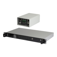
Camera Control Interface Unit - CRIU-ASSY-7XXX
Issue No: M Page: 22
Ref: FOCL-ASUM-8xxx Copyright © 2017 Vislink plc
Setup hardware configuration required:
1. Use either Wire or Fiber optic to connect the camera interface to the transmitter (not
both).
2. Connect an appropriate antenna to the transmitter.
CAUTION: Never allow the Transmitter unit to transmit without an antenna or dummy load
attached to the antenna connector.
3. Connect OCP/RCP’s to the interface unit
Interface Unit configuration:
Input – OCP
Output – TX Head
Interface unit RF configuration
Configure each OCP channel input as required:
a. Enabled – Yes/No
b. Camera ID – Same as data receiver
c. OCP – Type
d. Camera – Model number
e. Return data – Yes/No
f. 12V Supply – Power the OCP from the interface unit.
g. Tally enabled – Activate wet/dry Tally connection via interface unit
The amount of OCP Channels available are controlled by License. Each basic system is
automatically provided with one license activated (one OCP channel active).
You can view the active OCP channels using the following menu:
General>License>Current License
Additional Licenses can be requested and installed via the web browser or manually
entered via the unit menu.
The serial number of the unit or ‘Unit Key’ may be requested by Vislink to generate new
licenses.
Vislink Unit Key and Licenses are recorded in four parts (four sets of encrypted/scrambled
numbers/symbols).
 Loading...