User Manual Focal Point
Camera Control Interface Unit - CRIU-ASSY-7XXX
Issue No: M Page: 23
Ref: FOCL-ASUM-8xxx Copyright © 2017 Vislink plc
A maximum total of three Interface units can be connected together and configured to
operate with one Transmitter unit. This then allows the potential of using up to 18x
manufacturer OCP/RCP’s or 16x Vislink OCP5’s.
Loop the RS485 connections from the ‘Expansion’ connector.
CAUTION: This connector has a ‘DC Out’ that must NOT be connected when looping
Interface units.
You can also loop the Interface units from the Fiber or 3-pin XLR Data connection.
Set the additional Interface Unit/s as Output > RS485 and Unit ID > Slave X
NOTE: When using multiple OCP/RCP’s do not to duplicate OCP addresses/IDs.
You may connect a maximum of eight Transmitter units to one Interface unit. This allows
individual frequency and output power adjustment to each Transmitter unit.
You can connect one transmitter to the fiber connections directly to the Interface unit. Any
additional Transmitters must be connected either using the Vislink Expander Module (one
additional Tx unit per Module) or the Vislink 1U Multiway Expander Module (four
additional Tx units per Module).
The Expander module is connected to the port labelled “Expander” at the back of the
Interface unit (RS485 and DC connections).
The Expander module(s) provides fiber connections for the additional Transmitter unit(s)
and has a Loop Out connection to add more Expander Modules.
Set the Interface options using the following menu:
RF Setup> Configuration> Number of heads
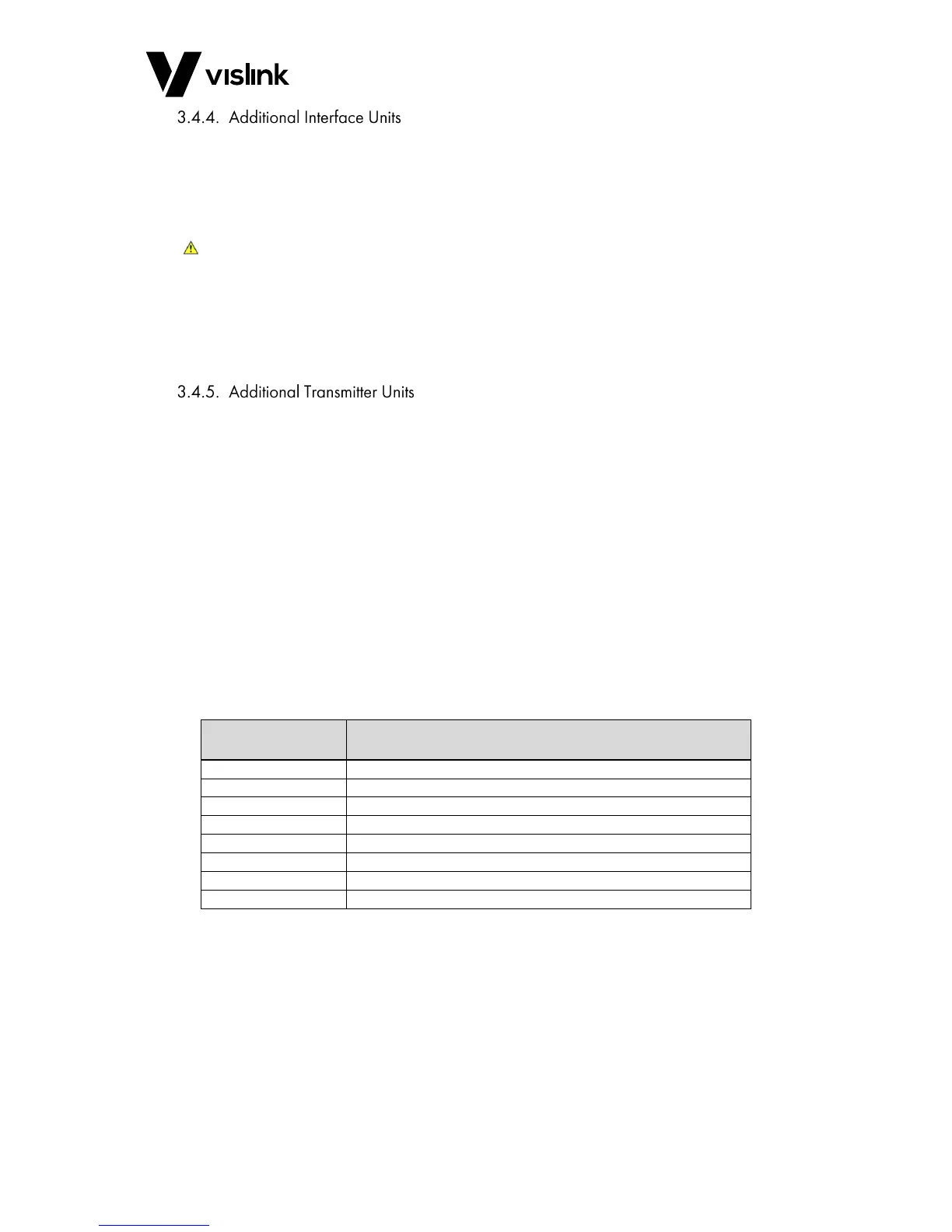
Table 3-6 Expander Module Part Numbers
NOTE: The Transmitter unit address switch must be set in relation to the amount of
Transmitter units being used. (Do NOT duplicate the address/ID).
 Loading...