DE6205 1
CL-8A, CL-8A T
Microprocessor Controlled Digital Keypads
Installation Instructions
1. INTRODUCTION
1.1 Description
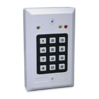
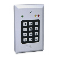
The CL-8A and CL-8A T (version with tamper
switch) are digital, code-operated keypads for
indoor access control and remote control
applications. The keypad can function with virtually
every security control panel on the market, and is
suitable for surface mounting or flush mounting in a
standard single-gang switchbox.
1.2 Features
• Self-contained, suitable for flush and surface mounting;
supplied with a surface mounting box.
• Includes a 10 A relay, which operates the door strike or
performs any desired switching function.
• Programmable on site by use of its own keyboard.
• Non-volatile EEPROM stores programmed data;
unaffected by power failure.
• Up to 56 different 1-8 digit user codes can be programmed.
• More than 100 million code combinations are possible.
• User codes may be individually deleted.
• Programmable AUXILIARY open-collector output with seven
powerful operating modes.
• Each user code programmable to operate the RELAY, or the
AUXILIARY output, or BOTH.
• Programmable relay contact closure duration; toggle (latch/
unlatch) mode may be selected if required.
• PANIC output triggered by pressing the # and
*
keys
simultaneously.
• Three built-in LED indicators.
• REQUEST TO EXIT remote input trips the relay with a remote
switch or a detector.
• A penalty timer locks out the keypad for 30 seconds after
three consecutive inputs of erroneous codes.
• An AMBUSH digit, if entered after the last digit of the user
code, sends a one-second pulse to the
PANIC output.
• 9 to 16 or 22 to 26 Volts AC/DC operation.
• Tamper switch option available.
2. SPECIFICATIONS
Code composition: 1 to 8 digits, any combination
Keypad type: 12 keys, 3 X 4, tactile operation
Operating voltage: 9-16 or 22-26 V AC/DC, selected with jumper
Current drain: 15 mA in the standby state, 55 mA with relay and
AUXILIARY output active
Power failure immunity: EEPROM retains all programmed
information even during total power loss
Other protections: Watch-dog protection from processor hang-up.
Relay control: Programmable for 1 – 98 seconds pull-in duration,
or for toggle (latching/unlatching) mode
Relay contact rating: 10 A / 30 VAC or DC
AUX and PANIC output current sinking: Up to 100 mA (each
protected by an 18 ohm series resistor)
LEDs: Green indicates keypad status
Red and yellow have 1K ohm series resistors and
terminals for external connections
Operating temperature range: -20°C to 65°C (-4°F to 149°F)
Size (H x W x D): 118 x 72 x 33 mm (4-5/8 x 2-3/16 x 1-3/8 in.)
Weight: 122 g (4.3 oz)
Color: White
3. INSTALLATION
3.1 Mounting
Do not install outdoors! Flush mounting is possible in standard,
single-gang electrical switch boxes (see Figure 1), without the
original back box. For surface mounting, use the back box
supplied with the unit (Fig. 2).
LOCKING
SCREWS
STANDARD, SINGLE-GANG
ELECTRICAL SWITCH BOX
Figure 1. Flush Mounting
MOUNTING
KNOCKOUTS
WIRING
KNOCKOUT
MOUNTING
KNOCKOUTS
BACK BOX
LOCKING
SCREWS
WIRING
KNOCKOUT
(1 OF 2)
Figure 2. Surface Mounting
3.2 Wire Gauges and Routing
Use # 20 AWG or larger diameters for relay connections to the
door strike, to the control panel or any other system used. All
other connections are to be made with # 22 AWG or larger. Route
the wires through the wiring knockouts on the back box.
3.3 Wiring
IMPORTANT! Before wiring be sure to set jumper JP3 in the position
that corresponds with the power source you are using:
9 - 16 Volts - mount the jumper across the two pins of JP3.
22-26 Volts - remove the jumper or mount it on a single pin of JP3.
The connections to the terminal block are shown in Figure 3.
–
+
N.O.
+
BUZ.
OR
REL.
DOOR
STRIKE
OR
RELAY
MAG-
NETIC
LOCK
12V OR 24 V
AC / DC POWER
SUPPLY FOR
THE CL-8
6 - 28 V AC / DC
DOOR CONTROL
POWER SUPPLY
+12 OR 24 VDC
RED LED YEL. LED
+
–+
+
–
BUZ.
OR
REL.
–
IMPORTANT:
when a 12 VAC
power source is used, LEDs
connected to the PANIC or AUX
open-collector outputs will light
normally when the output pulls
down. Buzzers will not function
properly, and should therefore
be avoided.
When a 24VAC power source is
used, neither LEDs nor buzzers
should be connected to the
PANIC and AUX outputs.
123456789101112
JP1
JP3
1K 1K
18
Ω
18
Ω
100 mA MAX.
100 mA MAX.
OPTIONAL TERMINAL BLOCK FOR CONNECTING OUTDOOR
KEYPAD KB-81 OR KB-82 (SEE PUBLICATION DE6215-)
*
**
***
Figure 3. Terminal Block Wiring