2 D-302413 NEXT PG2, NEXT K9-85 PG2 Installation Instructions
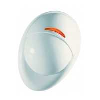
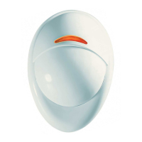
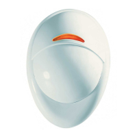
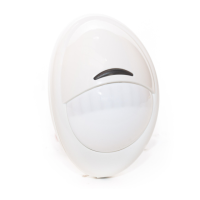
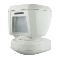
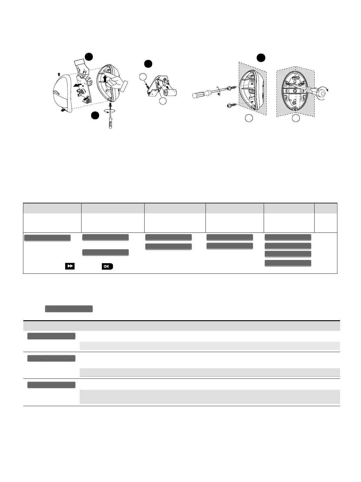
2.2 Mounting (see Fig. 3)
Notes:
1. Mount the detector so that its orientation is perpendicular to the expected intrusion path.
2. For installations of detector at 2m high, Dead zone is 2ft at 0m high and 0.5ft at 1.5m high.
1. Release screw and remove cover.
2. Push catch and remove board.
3. Insert battery.
4. Mounting
A. Front Tamper switch
B. Back Tamper switch.
C. On surface
D. In corner
Caution!
Risk of explosion if battery is replaced by an incorrect type. Dispose of used battery according to manufacturer's instructions.
Note: Back Tamper must be enabled for UL installations.Figure 3. Mounting
2.3. Enrollment
Refer to the PowerMaster panel's Installer Guide and follow the procedure under the "02:ZONES/DEVICES" option of the Installer Menu.
A general description of the procedure is provided in the following flow chart.
Enter the Installer menu
and select
“02:ZONES/DEVICES”
Select "ADD NEW
DEVICE" Option
See Note [1]
Enroll the device or Enter
the device ID
Select the desired Zone
Number
Configure Location,
Zone Type &
Chime Parameters
means scroll and select
Notes:
[1] If the detector is already enrolled you can configure the detector parameters via the “Modify Devices” option – see Step 2.
[2] Select the "Device Settings" option and refer to section 2.4 to configure the detector parameters.
2.4. Configuring the Detector Parameters
Enter the menu and follow the configuration instructions for the Next PG2 / Next K9-85 PG2 PIR detector as described in the
following table.
Configuration Instructions
Here you determine whether or not the alarm LED indication will be activated.
Optional settings: LED ON (default) and LED OFF.
Here you determine whether an alarm will be activated upon continued motion (low sensitivity) or upon a single
alarm event (high sensitivity)..
Optional settings: LOW sensitive (default) and HIGH sensitive.
Here you determine whether or not to set the activity time during disarm.
Optional settings: NOT Active (default), YES – no delay, YES + 5s delay, YES + 15s delay, YES + 30s delay,
YES + 1m delay, YES + 2m delay, YES + 5m delay, YES + 10m delay, YES + 20m delay and YES + 60m delay.